GD&T and ISO GPS
GD&T and ISO GPS
MD-Lab research on geometric dimensioning and tolerancing connects ISO GPS specification, functional performance, datum-system design, finite-element assembly behaviour and inspection strategy for compliant parts and additive-manufactured components.
- FEA + GPSfunctional tolerance specification informed by assembly deformation and contact response
- 12 mmbrace thickness still produced bolt-location deviations outside the initial tolerance zone
- 0.035 mmflatness deviation achieved for restricted FDM datum target areas in the AM case study
Impact
GD&T and ISO GPS are not only drawing languages. They are engineering decisions that determine how parts are manufactured, inspected, assembled and judged as functionally acceptable. When parts are stiff and simple, conventional tolerance choices may be adequate. When parts deform during assembly or are produced by additive manufacturing, the datum system and tolerance state can dominate functional performance.
MD-Lab’s work addresses this gap by connecting geometric specification with the real mechanical behavior of components. The research asks whether a tolerance zone should be defined in the free state, restrained state or assembled state, how datum features should be selected, and how inspection references should reflect the part’s actual function rather than only its nominal CAD geometry.
MD-Lab’s Research
The GD&T research program combines tolerance analysis, CAD reconstruction, nonlinear FEA, additive-manufacturing process interpretation and metrology-oriented datum design.
- Stiffness-aware specification: include part compliance, assembly loads and contact conditions in the tolerance-design process.
- Functional performance checks: evaluate whether critical features remain inside tolerance zones after deformation.
- ISO GPS state selection: distinguish free-state and restrained-state requirements for flexible or thin-walled components.
- AM datum strategy: use restricted datum features and datum targets to improve repeatability for additive-manufactured parts.
Stiffness-Aware Tolerance Specification
Functional assemblies often contain components that change shape when clamped, bolted or loaded. If GD&T requirements are assigned only on the free-state geometry, a part may appear unacceptable during inspection even though it works in assembly, or it may pass inspection while failing to meet functional alignment after deformation.
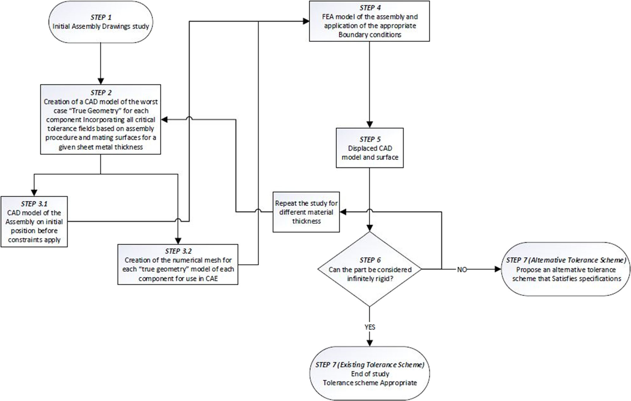
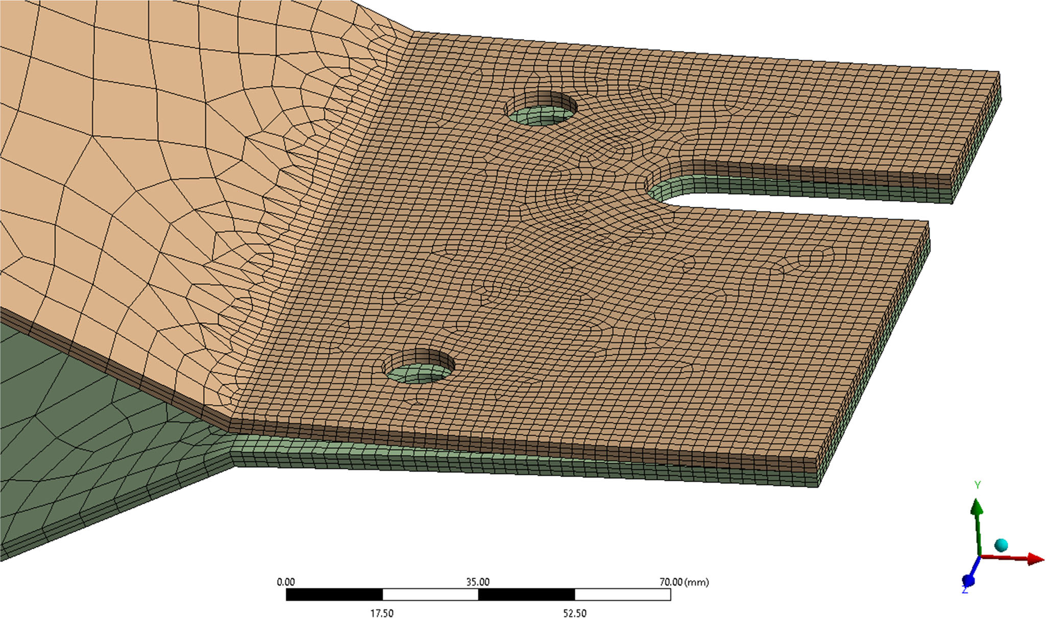
MD-Lab developed a computational workflow that introduces part stiffness into tolerance specification. The method starts from the technical drawing and nominal CAD model, reconstructs worst-case true geometry, and then uses nonlinear finite-element analysis with contact and functional loading to predict deformed feature locations. This allows the designer to compare free-state and assembled-state tolerance decisions before committing to manufacturing documentation.
- CAD and nonlinear FEA workflow for tolerance specification of compliant assemblies
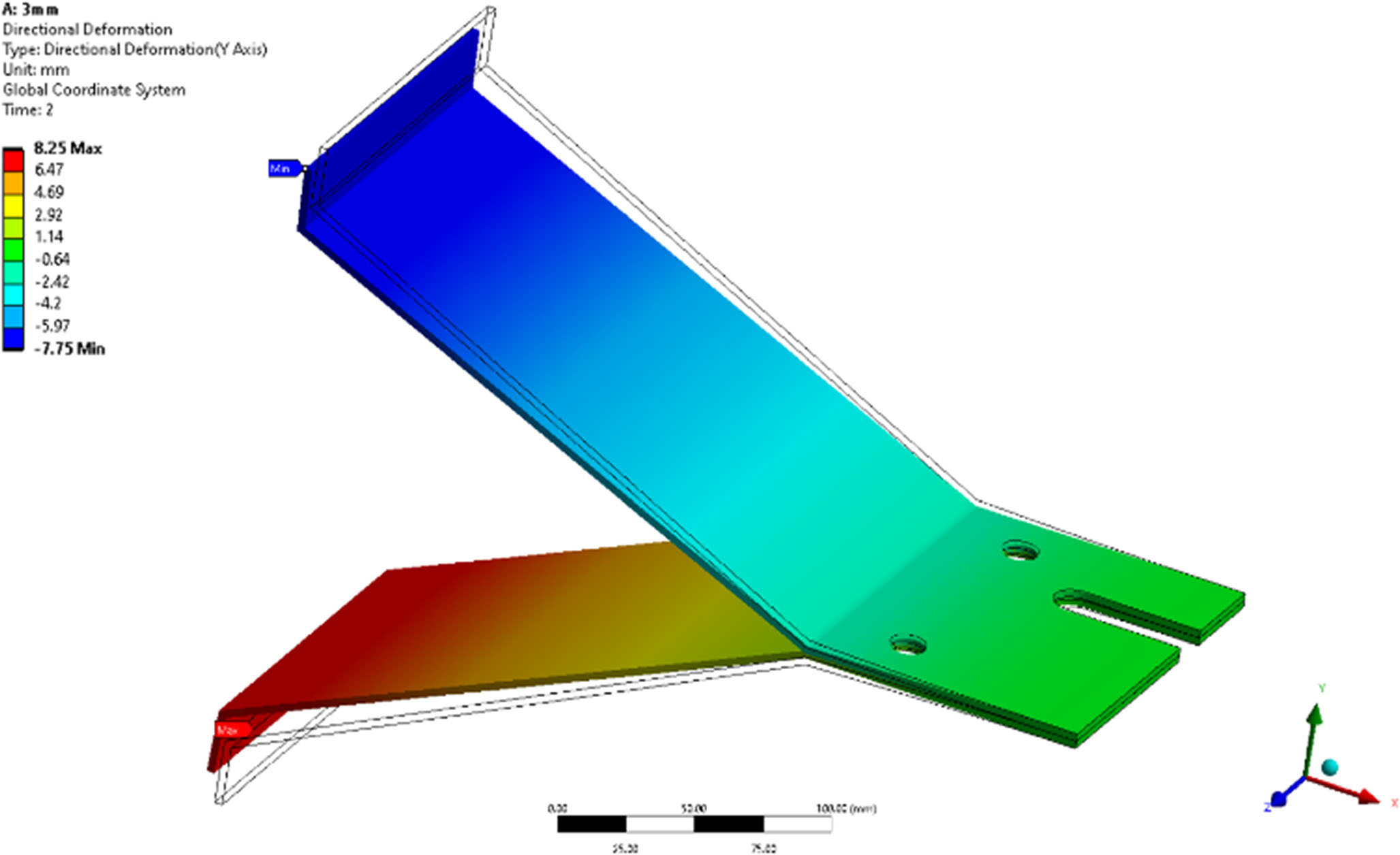
- Datum feature deviations shown to be strongly affected by functional loads and part stiffness
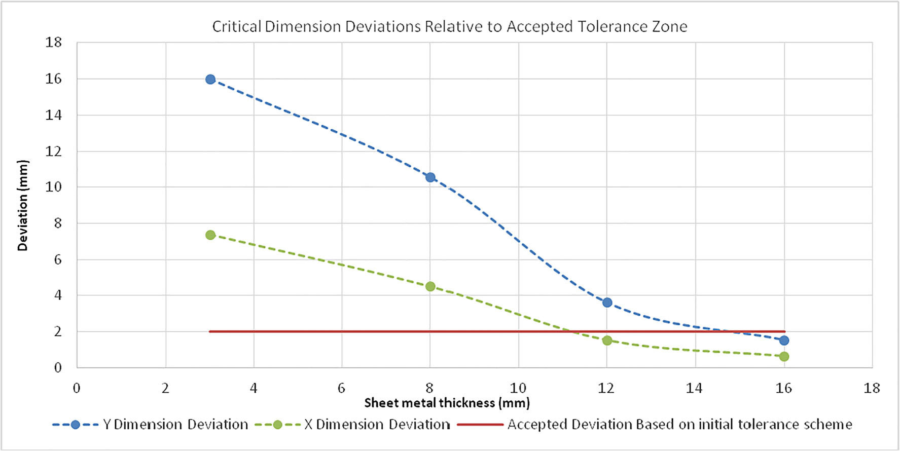
- M10 bolt-location deviations remained outside the initial free-state tolerance zone up to 12 mm sheet thickness
- Revised ISO GPS strategy proposed using free-state and constrained-state requirements
The case study on a sheet-metal brace assembly shows why tolerance specification must be linked to functional response. The analysis demonstrated that increasing thickness reduces deformation but does not automatically restore compliance with the original tolerance logic. A better specification can therefore come from changing the tolerance state and datum interpretation, not only from making the part stiffer.
Related Publications
- Mavridis-Tourgelis, A., Vakouftsis, C., Kaisarlis, G., Arampatzis, V. G., Provatidis, C. G., & Spitas, V. (2020). Computational implementation of part stiffness on tolerance specification based on the functional performance of assemblies. The International Journal of Advanced Manufacturing Technology, 111, 397-410. https://doi.org/10.1007/s00170-020-06139-3
Datum Systems for Additive Manufacturing
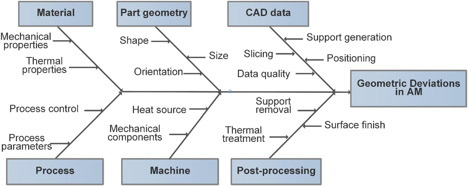
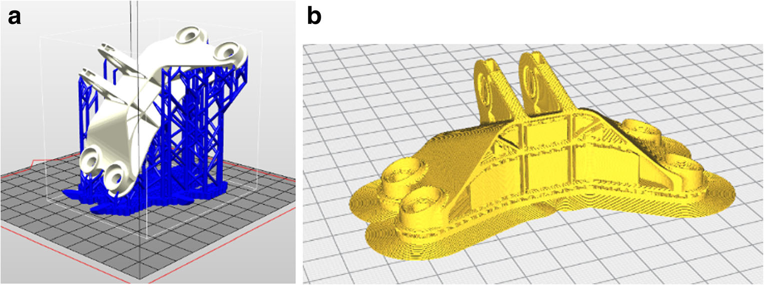
Additive-manufactured parts can contain geometric deviations caused by build direction, layer thickness, support structures, hatching strategy, material behavior and post-processing. These effects make datum-system selection especially important for functional components, because the chosen datum hierarchy determines how the part is oriented, inspected and assembled.
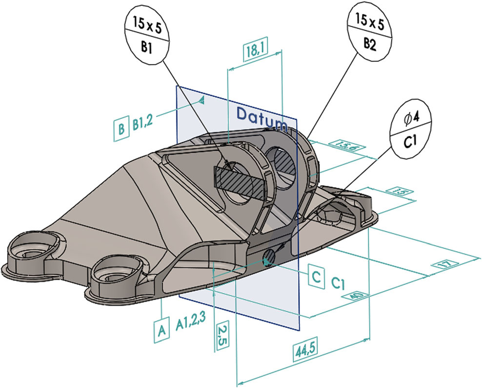
MD-Lab examined whether AM parts require process-specific datum standards or whether the existing ISO GPS framework can already express the necessary design intent. The research shows that existing tools are sufficient when they are used carefully: restricted datum features, datum targets and inspection-oriented reference areas can create more robust and repeatable datum systems for AM components.
- Systematic review and analysis of datum establishment for AM functional components
- Datum-system design connected to build direction, support strategy and inspection needs
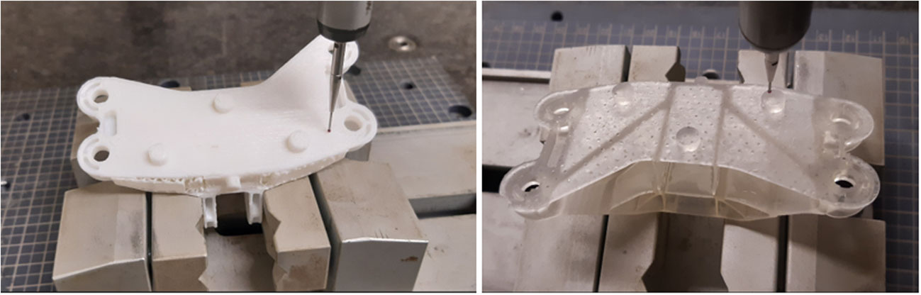
- Restricted FDM datum-target flatness deviation reduced from 0.23 mm to 0.035 mm
- Restricted SLA datum-target flatness deviation reduced from 0.51 mm to 0.082 mm
The case study demonstrates that smaller, functionally chosen datum target areas can behave better than full nominal planar datums on AM surfaces. This supports a design-for-accuracy approach in which GD&T, AM process planning and measurement strategy are treated together from the start.
Related Publications
- Vakouftsis, C., Mavridis-Tourgelis, A., Kaisarlis, G., Provatidis, C. G., & Spitas, V. (2020). Effect of datum system and datum hierarchy on the design of functional components produced by additive manufacturing: a systematic review and analysis. The International Journal of Advanced Manufacturing Technology, 111, 817-828. https://doi.org/10.1007/s00170-020-06152-6