3D-Printing Accuracy
Determining Material-Extrusion 3D-Printing Accuracy
MD Lab research on material-extrusion accuracy follows two complementary routes. One determines whether printed holes and shafts will assemble as intended through ISO-GPS coordinate metrology. The other determines printer performance through a compact self-assessment benchmark that turns cylinder form error into an accessible displacement measurement.
Engineering Need
Material extrusion is widely used for polymer prototypes and end-use parts, but assembly quality still depends on simple geometric features that must fit reliably: holes, shafts and other features-of-size. For these parts, dimensional accuracy affects interchangeability, clearance, assemblability and mechanical performance.
The research separates accuracy determination into two levels. Approach 1 works at component level, measuring printed cylindrical features with CMM data and ISO-GPS interpretation. Approach 2 works at printer level, using a low-cost benchmark layout for routine comparison of FDM machines and process settings without immediate access to a CMM or scanner.
Approach 1: Functional Feature Metrology
Determines fit-critical hole and shaft deviations using CMM data, ISO modifiers and regression compensation.
Approach 2: Printer Self-Assessment Benchmark
Determines printer accuracy with a printable base-slider-cylinder artifact and a simple displacement measurement.
Approach 1: Functional Feature Metrology
- Determines
- Size and cylindricity deviations of printed holes and shafts.
- Uses
- CMM probing, ISO 14405-1 size criteria and ISO 1101 form evaluation.
- Output
- Functional tolerance data and CAD compensation guidance.
Feature-of-Size Test Programme
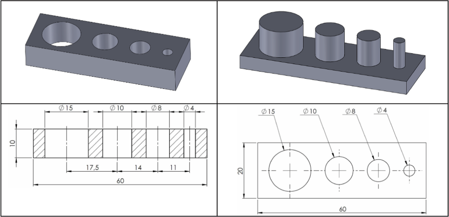
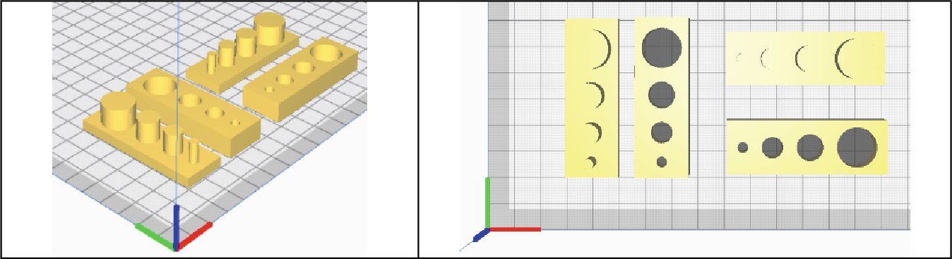
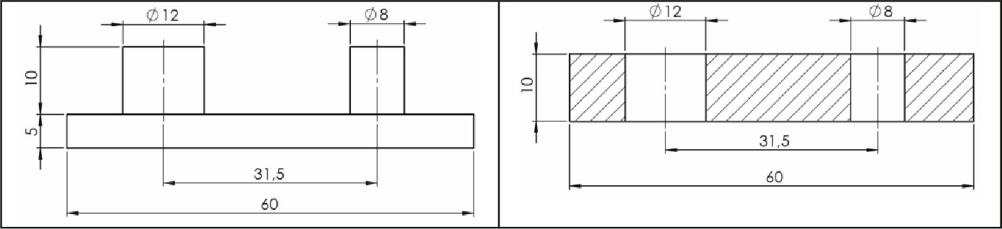
Two primitive test parts isolate the functional geometries that matter most in assemblies. Part 1 contains cylindrical hole features, while Part 2 contains matching shaft features. Nominal diameters of 4, 8, 10 and 15 mm make it possible to compare size-dependent behaviour across both mating geometries.
The specimens were produced on two material-extrusion platforms: ABS-M30 on a professional Stratasys Fortus 360 mc system with a controlled heated chamber, and PLA on a low-cost Creality Cr10s5 platform. Each material/printer combination was fabricated in horizontal and vertical orientations to separate material, geometry and build-direction effects.
ISO-GPS Measurement Strategy
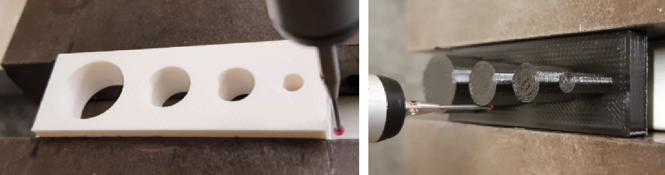
Dimensional and geometrical evaluation used a bridge-type HEXAGON MI Mistral 070705 CMM installed in a temperature-controlled laboratory area at 20 ± 0.5 °C. A Renishaw PH10M head with TP2 touch-trigger probe and a 1.5 mm ruby-ball stylus collected 40 contact points per feature in a helical pattern. Each feature was measured six times, producing average size and form values for 32 evaluated features.
The key metrology choice is the use of function-relevant ISO 14405-1 association criteria. Hole diameters are evaluated with the maximum inscribed fit, GX, while shaft diameters are evaluated with the minimum circumscribed fit, GN. This reflects the actual assembly condition: the functional hole diameter must remain larger than the mating shaft diameter.
Measured Deviations in ABS and PLA
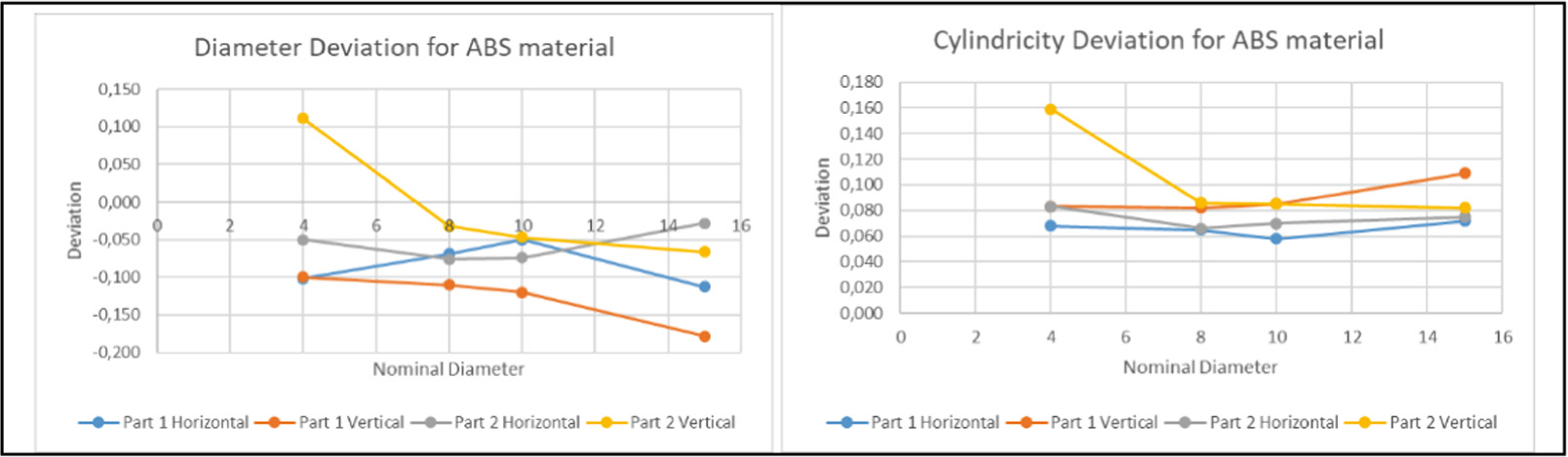
ABS results show stronger sensitivity to part geometry and build condition. Hub features generally shrink more than shaft features, while cylindricity is influenced by nominal size, geometry and orientation. The 4 mm vertically printed shaft is a notable outlier, underlining the difficulty of small functional features in material-extrusion parts.
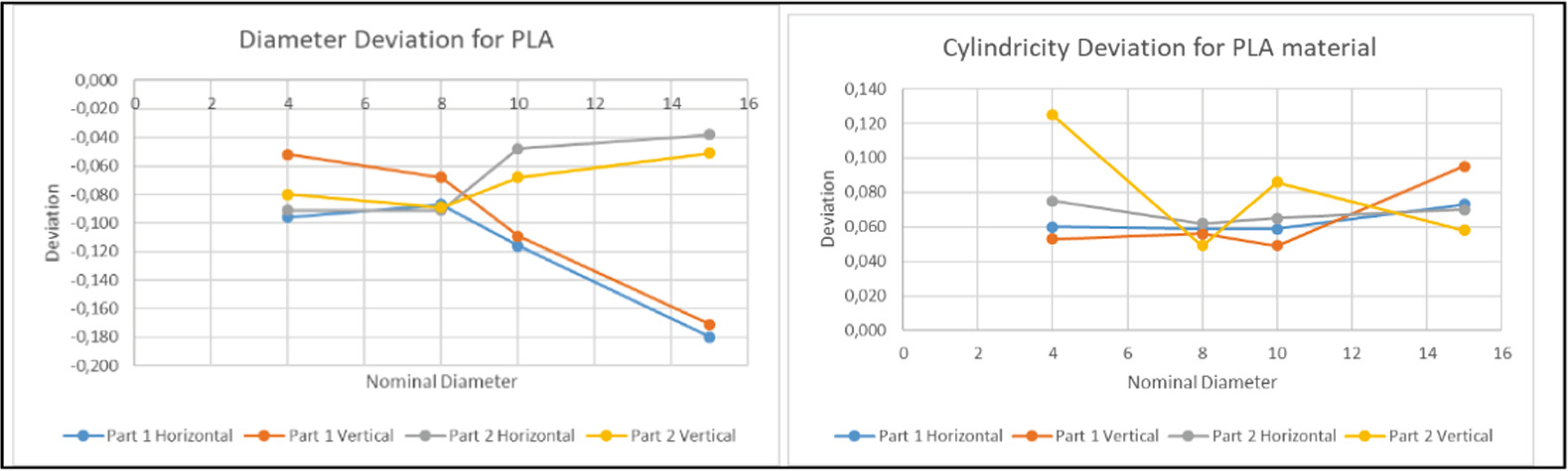
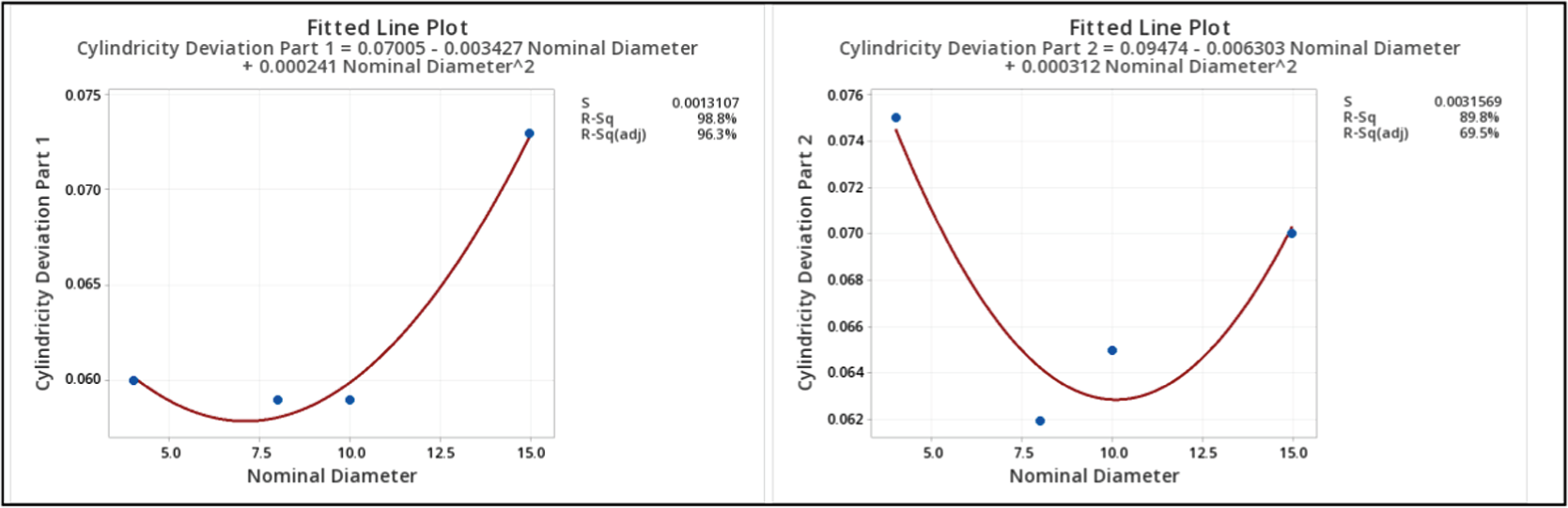
PLA results are more stable in cylindricity, fluctuating around an average value of approximately 0.068 mm across the investigated sizes and orientations. Diameter deviations remain geometry-dependent, with hub features tending to shrink more than shaft features. Horizontal orientation often gives slightly smaller deviations than vertical orientation, but feature geometry remains the more influential factor in the tested set.
The dominant error source is linked to thermal stress during solidification and cooling. Printer repeatability and process-parameter optimization remain important variables for later model refinement.
Predictive Tolerancing
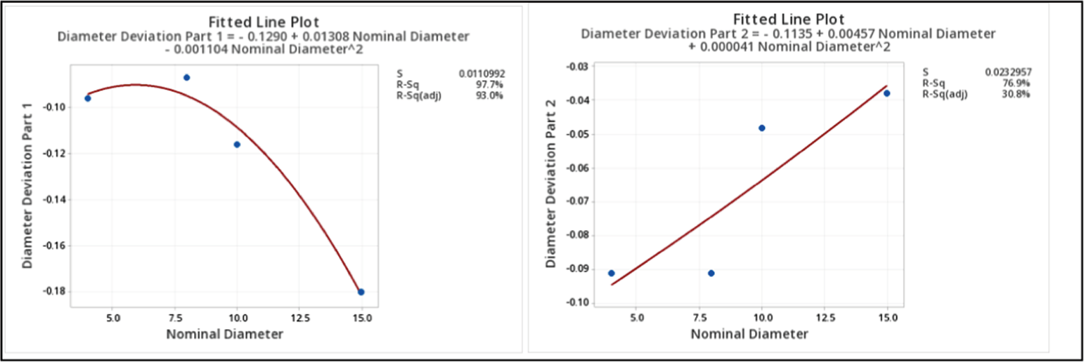
The same measurement data can be used as a design input. For PLA parts printed in horizontal orientation, regression equations describe expected diameter and cylindricity deviations of hub and shaft geometries. This supports compensation of functional diameters before printing.
For a 12 mm example, the regression model estimates a hub diameter deviation of -0.131 mm and a shaft diameter deviation of -0.0528 mm, with cylindricity deviations close to 0.063-0.064 mm. Depending on the required clearance, the designer can adjust the CAD diameters of the hub, the shaft or both. The drawing should also indicate ISO 14405-1 linear sizes and apply the GX and GN modifiers to the relevant hole and shaft specifications.
Approach 2: Printer Self-Assessment Benchmark
- Determines
- Printer-level diameter and cylindricity accuracy trends.
- Uses
- A printable base, slider and cylinder with inclined contact surfaces.
- Output
- A displacement-based accuracy indication for quick comparison.
Benchmark Layout
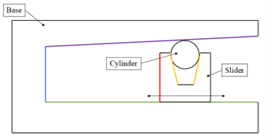
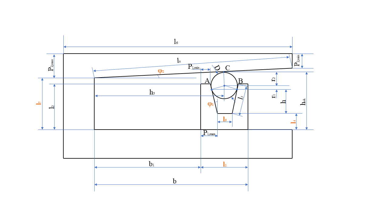
The second approach determines printer accuracy through a dedicated benchmark assembly instead of direct inspection of a final functional part. The layout uses three printed components: a base, a slider and a cylinder. The cylinder sits in a V-groove on the slider and contacts an inclined surface on the base.
Rotating the cylinder changes how its local diameter seats in the V-groove. That vertical change produces lateral motion of the slider, turning small cylindricity and diameter deviations into an easier-to-measure displacement. This makes the approach suitable for quick printer self-assessment and setting-to-setting comparison with simple measuring tools.
Geometric Amplification and Validation
A geometric model relates the measured slider-base distance to the apparent cylinder diameter. Contact points on the two V-groove faces and the inclined base surface define the measurement geometry. A shape factor captures the effect of slope angles: steeper slopes reduce sensitivity, while gentler slopes increase amplification.
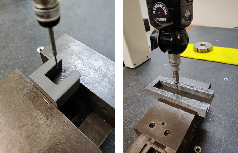
The benchmark and cylindrical specimens were produced from PLA on a Creality Ender 3 FDM printer using 0.2 mm layer height, 200 °C nozzle temperature, 50 °C bed temperature, 20% infill and four wall layers. The base and slider were measured by CMM, and their dimensional deviations were fed back into the geometric model.
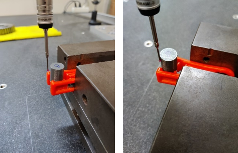
Twenty printed cylinders were evaluated through CMM measurement, caliper checks and the benchmark layout. CMM validation at the Machine Design Laboratory of NTUA used 30 sampled points along each cylinder surface and PC-DMIS processing according to ISO 1101. The benchmark followed the CMM trend with an approximately consistent offset of 0.025 mm, positioning it as a practical comparison method rather than a replacement for full coordinate metrology.
Engineering Significance and MD Lab Contribution
Keeping the two approaches separate clarifies their engineering use. Approach 1 answers a component-level question: will these printed holes and shafts fit as intended? Approach 2 answers a printer-level question: is this FDM machine and process setting producing consistent cylindrical geometry?
The technical contribution combines custom feature-based specimens, controlled material-extrusion trials, coordinate metrology, ISO 14405-1/ISO 1101 interpretation, geometric amplification and regression-based prediction. The current models are limited by the tested feature ranges, printer settings and materials, but they create a practical framework for extending both approaches to other polymers, AM technologies, process parameters and geometric deviation types.
MD Lab’s role is reflected in the NTUA laboratory affiliation and validation workflow. The Machine Design Laboratory participates in the FDM printer self-assessment direction and provides CMM-based reference measurements for the cylindrical validation specimens, linking accessible workshop-level assessment with traceable coordinate metrology.