Double Flank Gear Roll Testing
Double Flank Roll Testing Method
MD-Lab research on double-flank roll testing converts a fast industrial gear inspection method into a richer diagnostic tool. The work links radial composite error measurements with numerical simulation of free-form meshing gears and inverse models for identifying gear-parameter deviations.
Impact
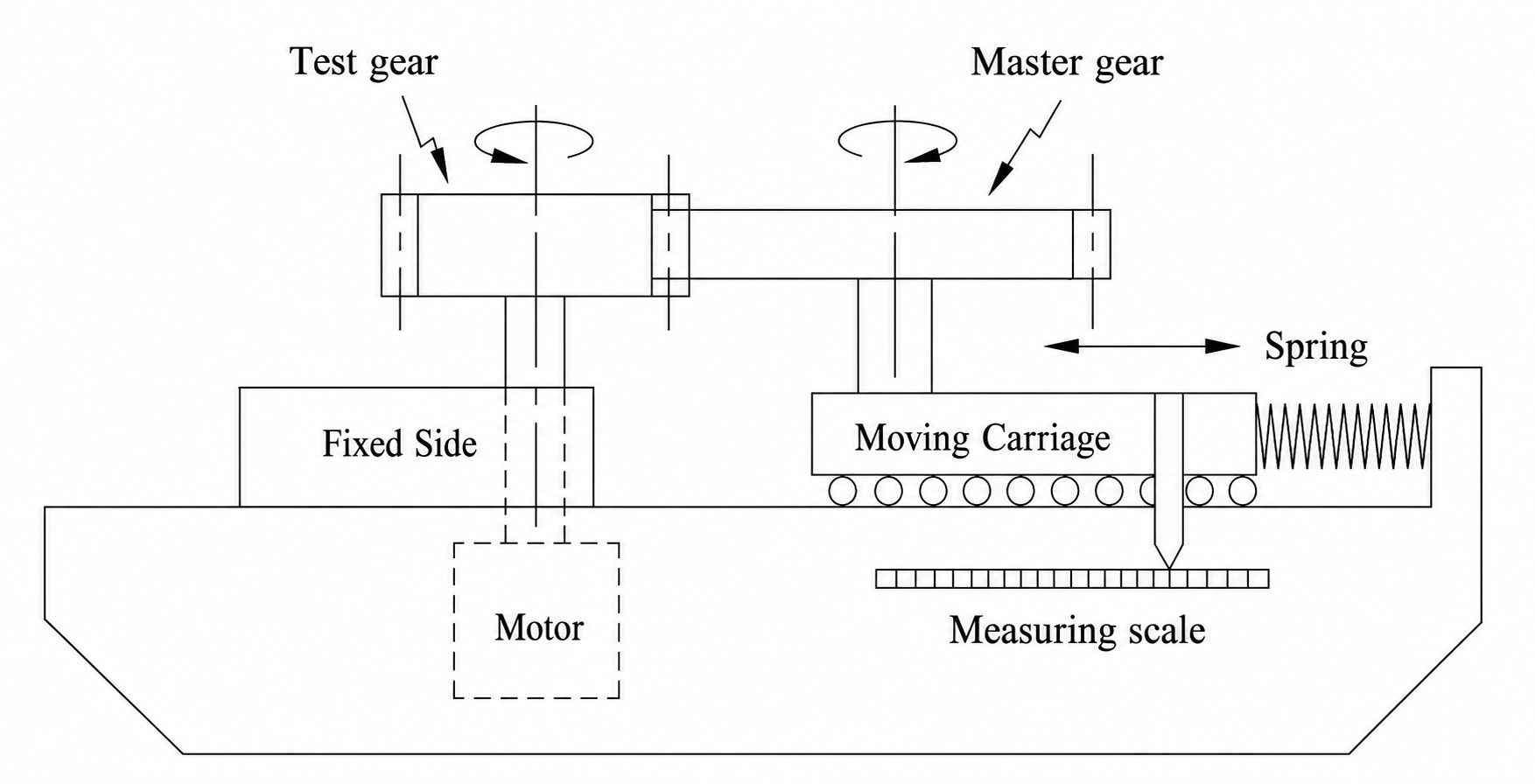
Double-flank roll testing is widely used in gear manufacturing because it is fast, robust and comparatively inexpensive. A test gear is rolled in tight mesh against a master gear and the variation of center distance is recorded as radial composite error. This provides a functional quality signal, but by itself it does not directly reveal which geometrical deviations produced the measured response.
The MD-Lab work addresses this limitation by connecting measured composite error charts to gear geometry. Instead of treating double-flank testing only as a pass-fail inspection method, the research develops simulation and inverse-analysis tools that can extract quantitative information about deviations such as pressure angle and space-width half-angle, while accounting for profile modifications, wear, flankline deviations and measurement uncertainty.
MD-Lab’s Research
The research program expands the information content of radial composite inspection.
- Forward simulation: simulate double-flank roll testing for spur gears with arbitrary tooth-flank geometries.
- Contact search: determine center-distance variation through working- and coast-flank contact without requiring special treatment of singular tip contacts.
- Experimental validation: compare roll-test measurements with CMM-derived geometric data and simulation boundaries.
- Inverse identification: use genetic algorithms to estimate gear-parameter deviations from selected points on the composite error chart.
Ongoing Research
The next stage of the work focuses on extracting richer geometric information from the same fast double-flank measurement signal.
- CMM-like flank reconstruction: determine tooth-flank profile deviations from double-flank measurements with diagnostic detail closer to analytical CMM inspection.
- Neural-network curve matching: train neural-network models to associate radial composite error curves with the geometric deviations that generated them.
Numerical Model of Double-Flank Roll Testing
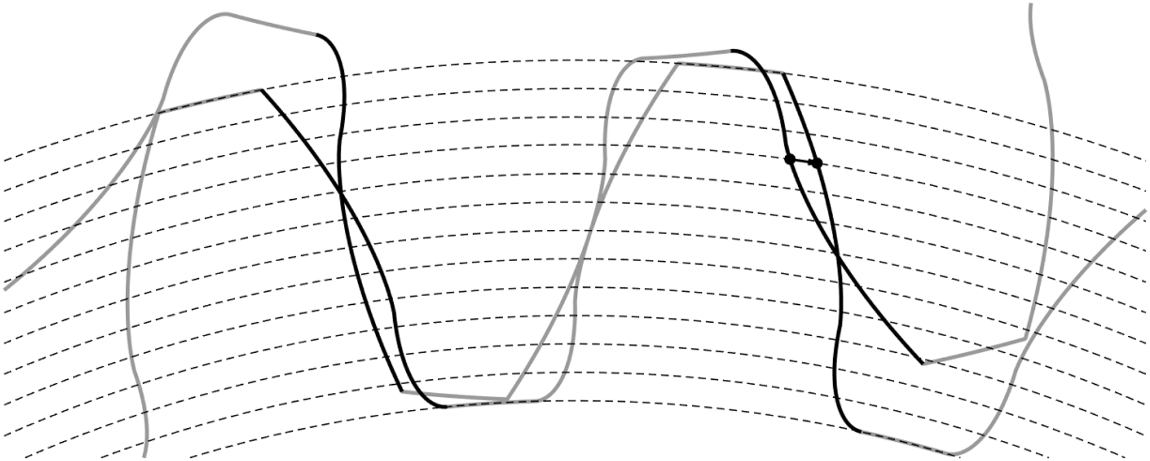
The forward model reproduces the tight-mesh inspection process between a test gear and an error-free master gear. The tooth flanks are represented as point clouds rather than being restricted to ideal involute equations, allowing the same algorithm to handle nominal teeth, parameter deviations, profile modifications, wear and non-involute flank shapes.
For each angular position of the driving gear, the model searches for the translational and angular displacement of the driven gear that produces contact without penetration between both working and coast flanks. The resulting center-distance variation is the simulated radial composite error chart measured in a double-flank tester.
- Generalized free-form flank representation for arbitrary tooth geometry
- Tight-mesh contact model including working and coast flanks
- Regula-Falsi convergence used for efficient center-distance calculation
- Simulation of pressure-angle, space-width, profile relief, wear and waviness effects
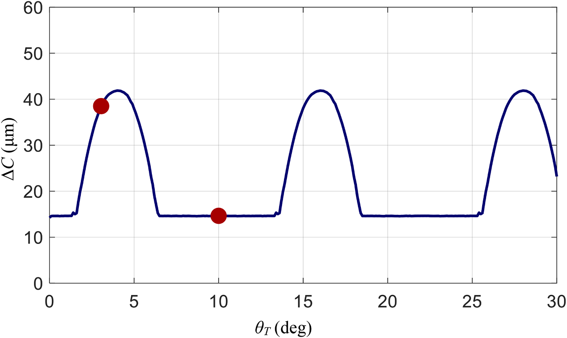
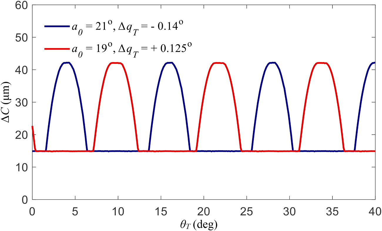
The simulations show how different parameter deviations create distinct composite-error patterns. Combined pressure-angle and space-width deviations, for example, produce recurring peaks whose position and amplitude encode information about the underlying gear geometry.
Related Publication
- Kalligeros, C., Papalexis, C., Vasileiou, G., Tzouganakis, P., Spitas, C., & Spitas, V. (2023). Exploiting double-flank roll testing spur gear measurements to determine gear parameter deviations through numerical simulation of free-form meshing gears. Simulation Modelling Practice and Theory, 126, 102757. https://doi.org/10.1016/j.simpat.2023.102757
Experimental Validation
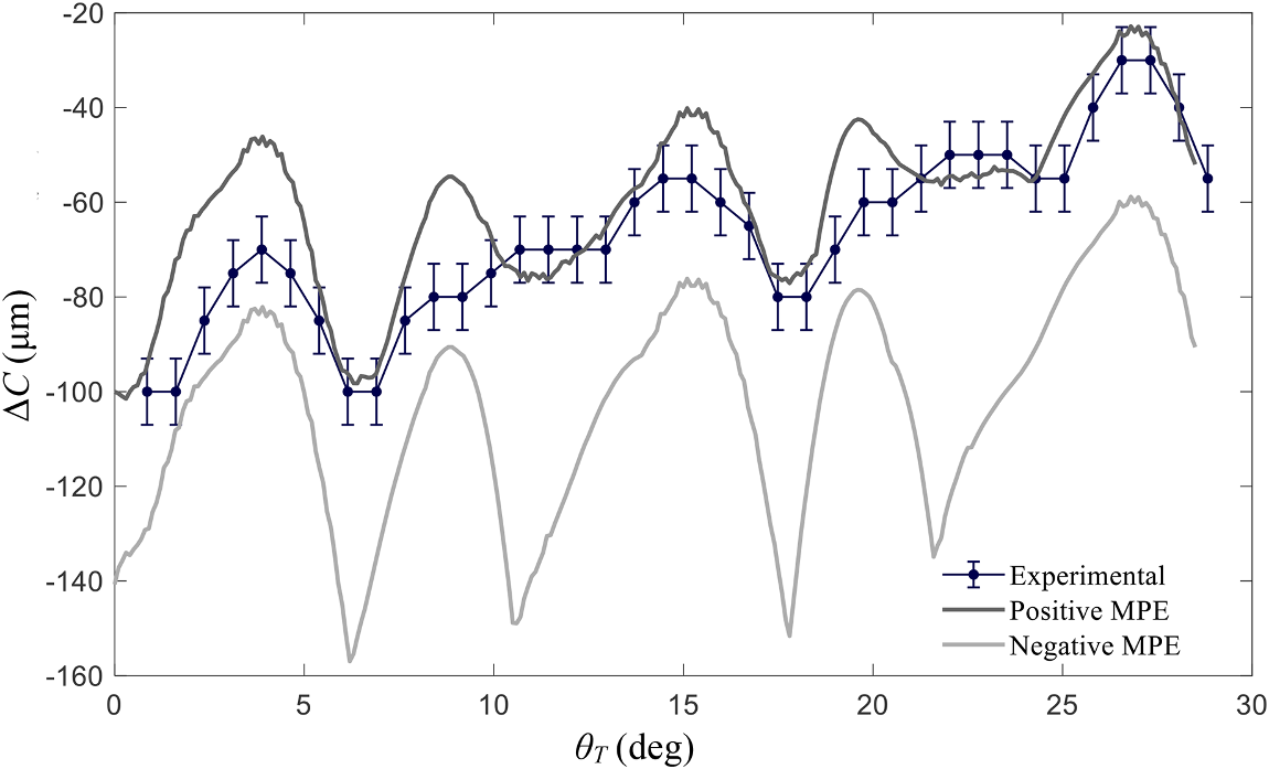
The simulation model is validated with original experimental data from double-flank roll testing and coordinate measurement. The test and master gears are measured analytically with a CMM, and the measured flank profiles are used as inputs to the forward simulation. This allows the model to generate upper and lower composite-error boundaries that include the CMM maximum permissible error.
The experimental roll-test results fall within the predicted simulation envelope. This agreement confirms that the free-form meshing model can reproduce the composite-error behavior of real gears, including the effects of manufacturing deviations that are not captured by ideal involute geometry alone.
- Goulder Mikron double-flank roll-testing measurements used for validation
- CMM-measured test and master gear profiles used as simulation input
- Positive and negative measurement-error boundaries propagated into the simulated response
- Experimental radial composite error shown to follow the predicted bounds
This validation step is important because the inverse method depends on the forward model. If the simulation can reproduce measured composite-error charts from measured flank geometry, it becomes credible to reverse the process and estimate unknown gear parameters from roll-test data.
Inverse Model for Gear-Parameter Deviations
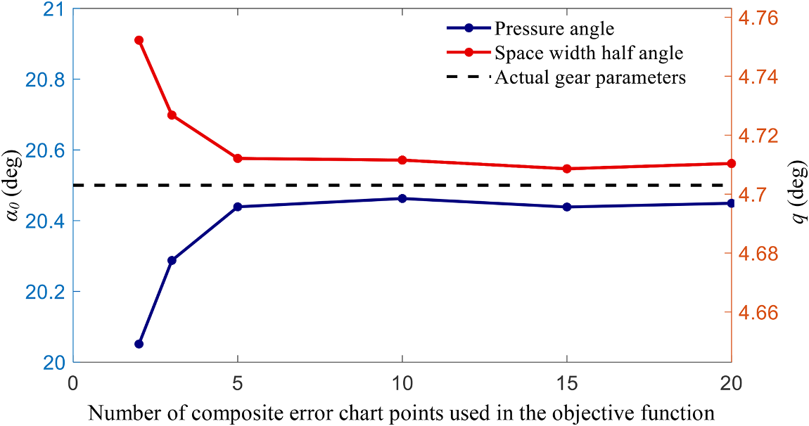
The inverse model uses the forward simulation inside a genetic-algorithm search. A set of points is selected from the composite-error chart, and the algorithm searches for the gear-parameter combination whose simulated center-distance variation best matches those measured points.
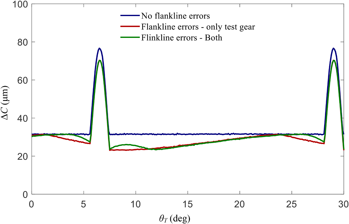
In the reference study, the inverse method estimates pressure angle and space-width half-angle from double-flank roll-test information. The reported prediction error is 0.005% for pressure angle and 0.025% for space-width half-angle in the ideal reference case. The model is then tested under random measurement fluctuations and flankline deviations to understand when additional chart points are needed for robust convergence.
- NSGA-II genetic algorithm used for inverse identification
- High accuracy retained for random fluctuations below 0.5 µm
- Convergence achieved with five chart points in a flankline-deviation case
- 0.198% prediction error reported when deviations of both gears were included
The conclusion is deliberately practical: double-flank testing cannot replace analytical inspection for arbitrary local profile errors, but it can reveal more than a simple composite quality grade. With simulation-based deconvolution, it can identify important global gear parameters and extend the value of an already common industrial inspection process.