UAV Testing and Validation
UAV Testing and Validation
Laboratory testing and simulation support for maritime unmanned aircraft prototypes
MD-Lab provided laboratory testing and engineering validation for maritime UAV prototypes developed with A.S. Prote Maritime Ltd. The work covered prototype preparation, static structural checks, dynamic vibration measurements, FFT-based response processing, reverse engineering and aerodynamic simulation support, creating a coherent pathway from physical testing to numerical validation.
Purpose and MD-Lab Role
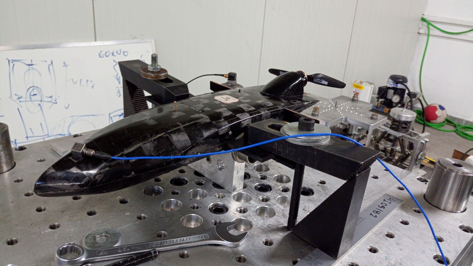
The project required a practical validation path for unmanned aircraft prototypes with different airframe configurations. MD-Lab received prototype hardware and related components, prepared them for laboratory measurement, and developed test cases that reflected realistic structural, dynamic and aerodynamic loading conditions.
The work combined hands-on experimentation with simulation support. Laboratory measurements provided the physical response data, while finite-element and CFD models helped interpret the behavior of the prototypes and refine the engineering assessment.
Static and Dynamic Testing
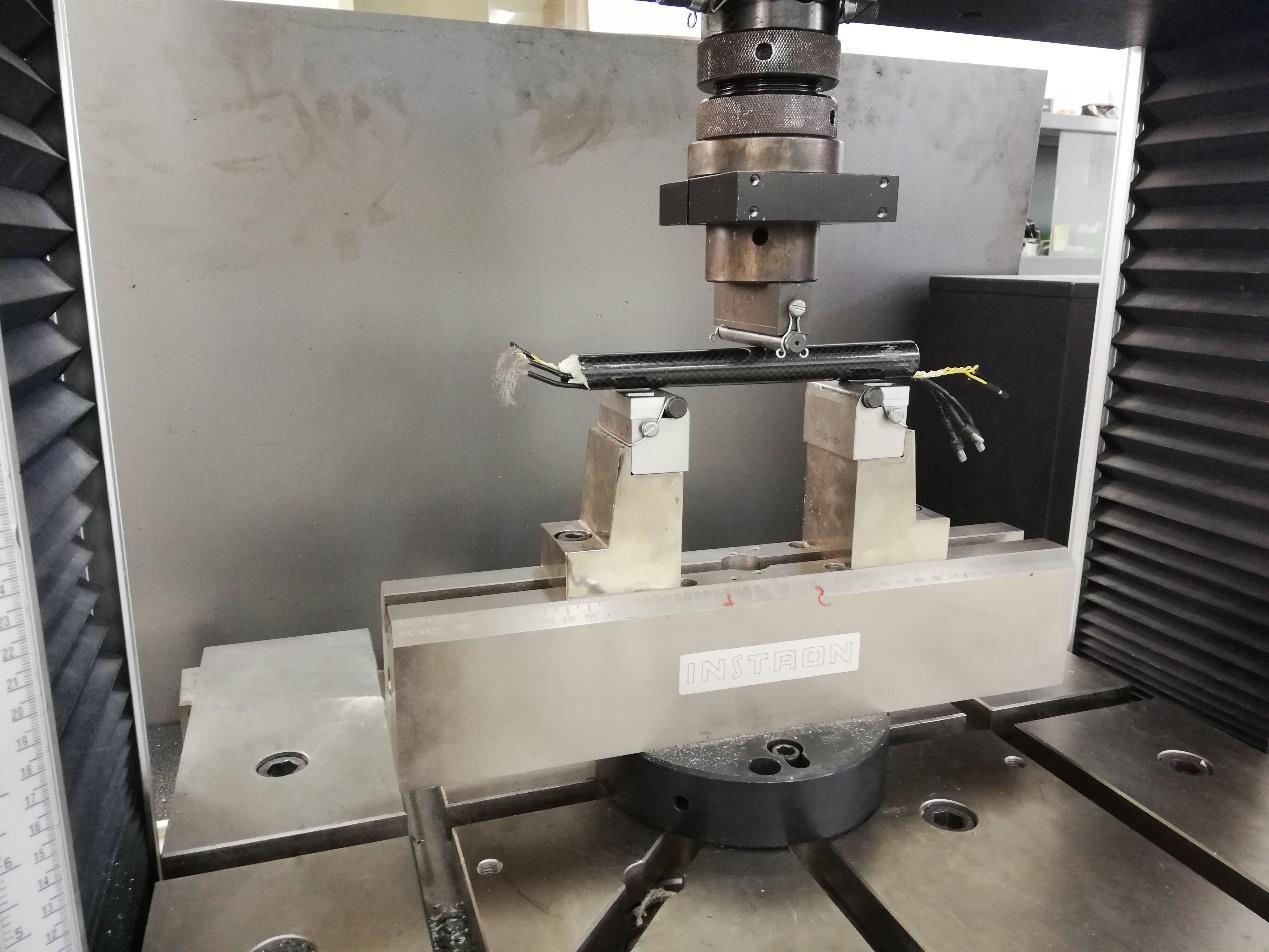
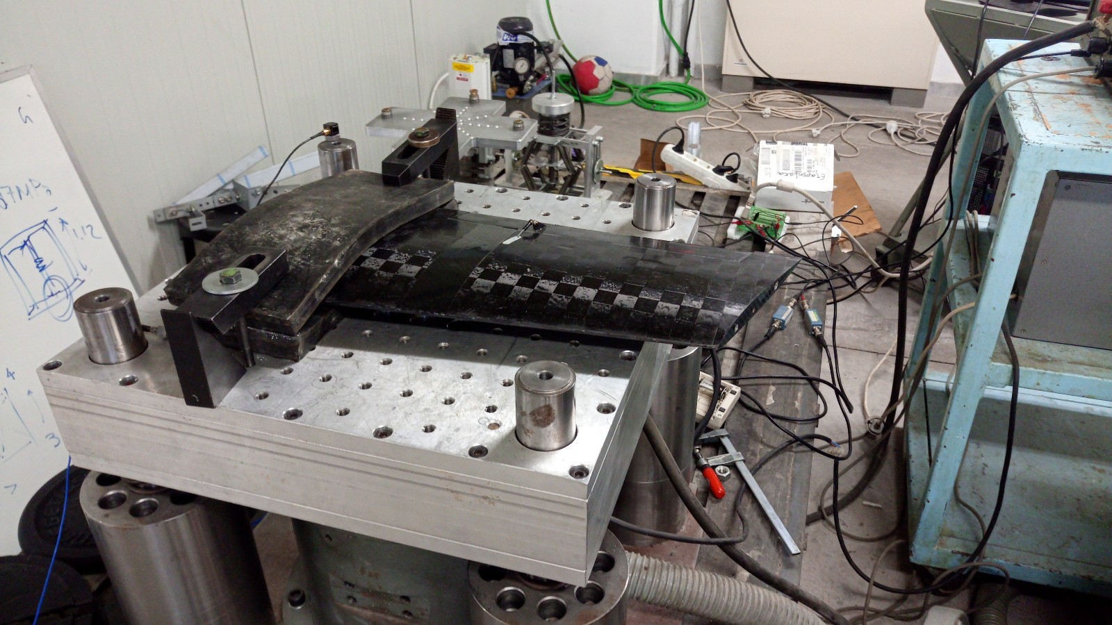
MD-Lab carried out a combined physical-test and simulation workflow. Static testing focused on representative carbon-fibre parts and prototype fragments, using bending configurations to examine structural behavior and manufacturing quality.
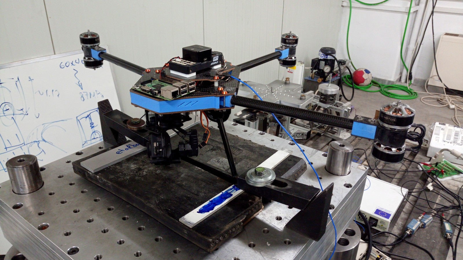
Dynamic testing used the DERRITRON electromagnetic exciter and dedicated fixtures to impose controlled vibration on prototype assemblies. The measurement workflow included frequency scans, impact-response tests, accelerometer and non-contact vibration measurements, and FFT-based analysis in LabVIEW and MATLAB. Finite-element harmonic-response and modal analyses were used as a numerical counterpart to the laboratory measurements.
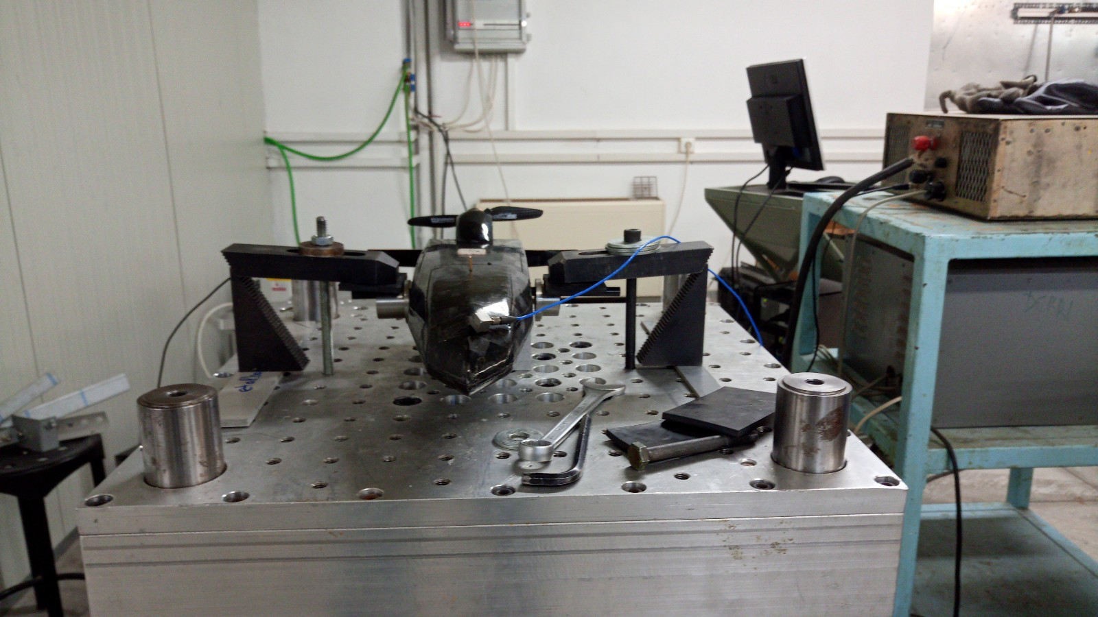
Measurement Chain and Data Handling
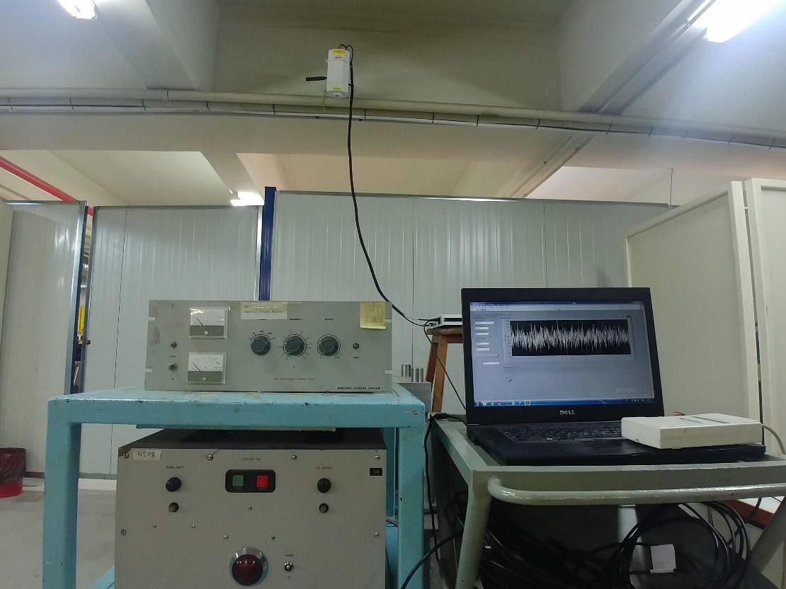
The measurement chain combined controlled excitation, sensor acquisition and repeatable post-processing. MD-Lab used an NI USB-6211 data-acquisition system, LabVIEW interfaces, MATLAB processing scripts and laser Doppler vibrometry to structure the measurements around traceable signals rather than visual inspection alone.
This workflow allowed the team to move consistently from raw time signals to frequency-domain interpretation. Repeatable mounting, calibrated measurement paths and structured post-processing made the experimental data suitable for comparison with computational models.
Geometry Preparation for Aerodynamic Testing
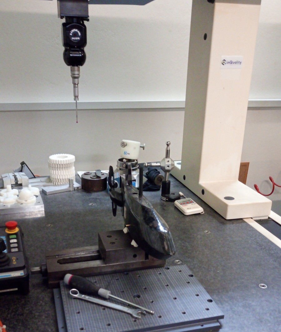
Before the aerodynamic simulations could be trusted, the UAV geometry had to be reconstructed and simplified in a controlled way. MD-Lab supported the reverse-engineering workflow using coordinate-measuring-machine data and post-processing in GeoMagic Design, so that the aerodynamic surfaces could be represented with sufficient fidelity for meshing and analysis.
CFD and Aerodynamic Simulation Support
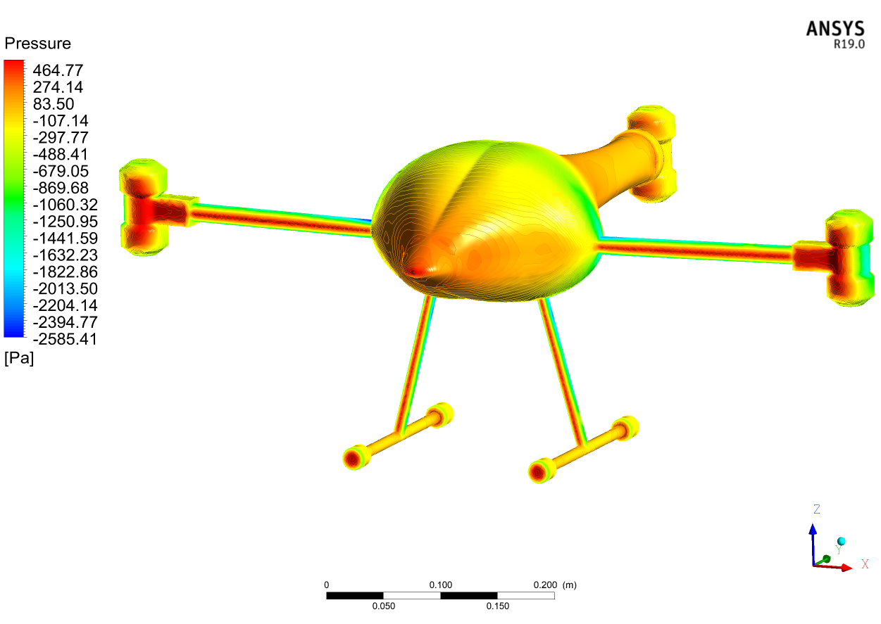
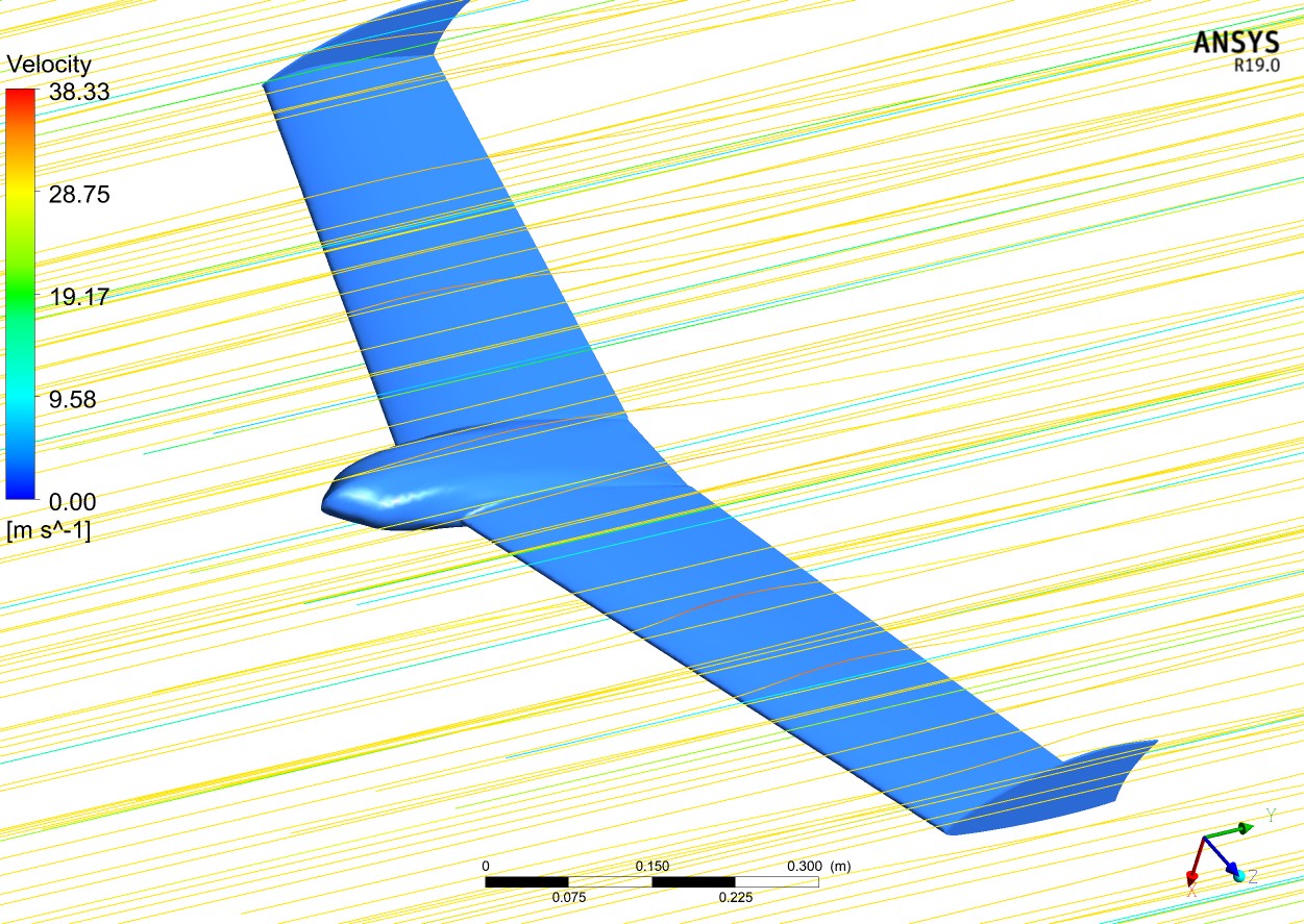
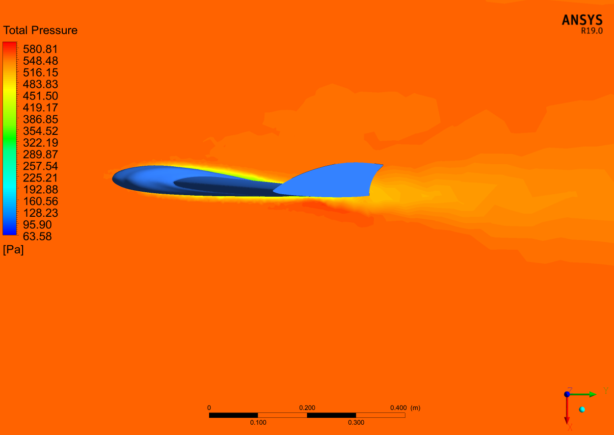
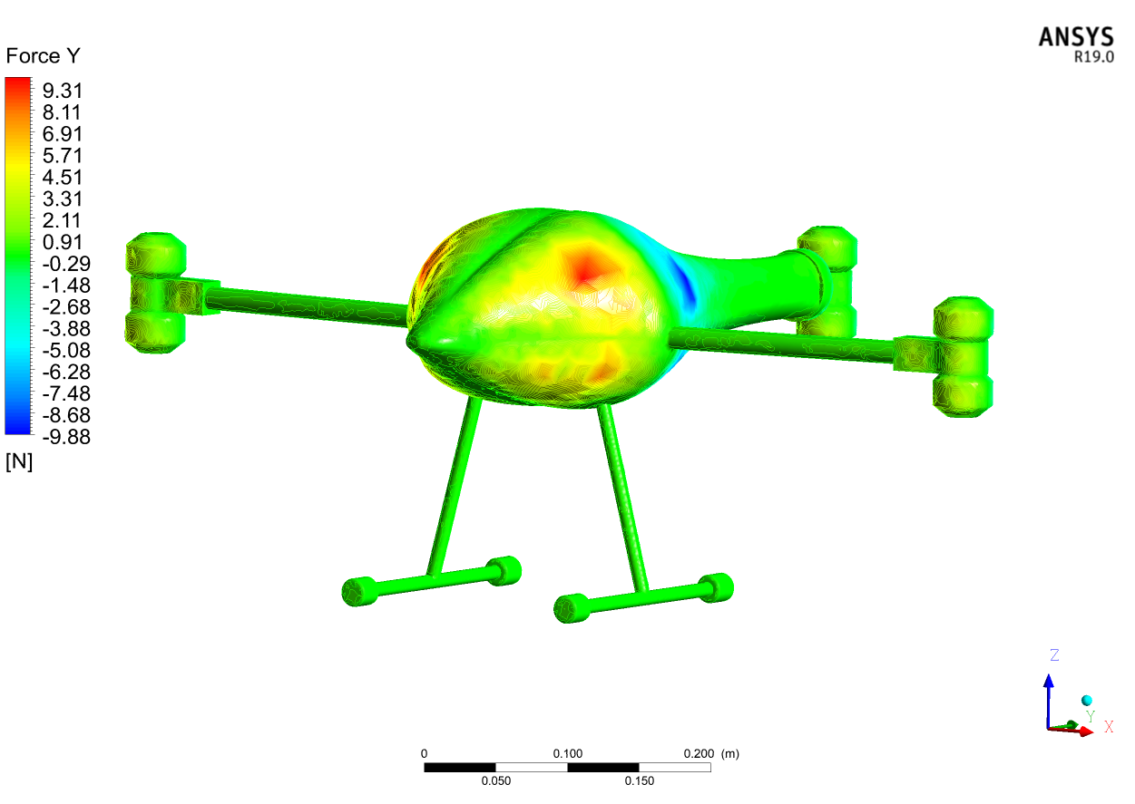
MD-Lab supported the aerodynamic side of the validation through semi-analytical and CFD workflows, including XFLR5 studies, ANSYS Workbench geometry preparation, mesh generation and ANSYS Fluent simulations. The simulations treated the surrounding air domain explicitly, using boundary conditions and turbulence modelling appropriate for the UAS geometries.
The images below show representative CFD outputs from the aerodynamic workflow, including surface pressure, wake behavior and streamline visualizations. Together with the laboratory measurements, these simulations supported a clearer understanding of the prototype response under flight-relevant conditions.