Pumpless Rankine Cycle System
Pumpless Rankine Cycle Systems for Low-Grade Heat Recovery
The Pumpless Rankine Cycle project develops compact power-generation technology for low-grade waste heat without the conventional mechanical pump of an organic Rankine cycle. MD-Lab combined applied system design, laboratory implementation and multi-domain dynamic modelling of heat exchange, valve switching, natural circulation, pressure transients and expander response.
Project Scope
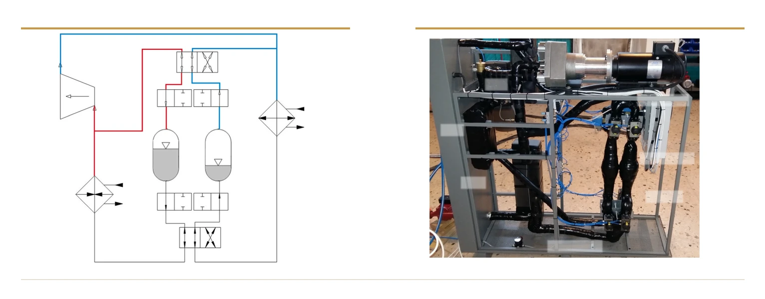
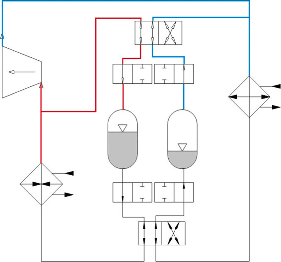
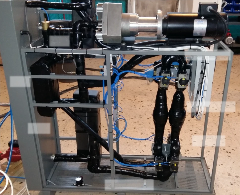
The project implements a pumpless Rankine Cycle that replaces the conventional mechanical pump of an organic Rankine cycle with a passive pressurization and switching architecture. Two buffer vessels alternate roles through a valve network, supplying liquid to the evaporator while the opposite side is filled from the condenser. The concept targets low-exergy heat recovery applications, where pump work, maintenance and control complexity can limit the practical value of small-scale power generation.
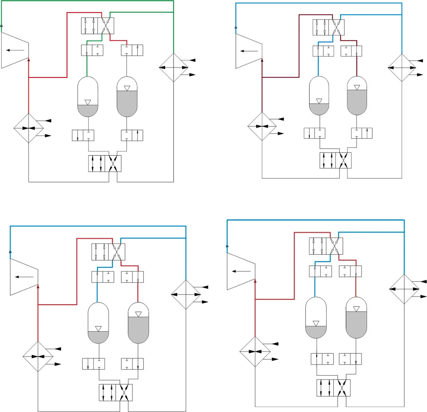
Unlike a conventional steady-flow ORC, the PRC operates through repeated switching phases, transient pressure redistribution, natural-circulation hydraulic behavior and heat-exchanger dynamics. These coupled effects shaped the engineering workflow, linking thermodynamics, fluid mechanics, machine dynamics and control timing into one design problem.
MD-Lab’s Contribution
MD-Lab delivered a complete dynamic modelling and validation workflow for the PRC system:
- Thermodynamic modelling of the evaporator, condenser and buffer-vessel pressure states.
- Natural-circulation hydraulic modelling for the liquid-side recovery loop.
- Valve-switching logic for alternating buffer operation without mechanical pumping.
- Experimental comparison against measured pressure, rotational-speed, output-power and efficiency data.
Cycle Architecture
Passive Pressurization and Alternating Buffers
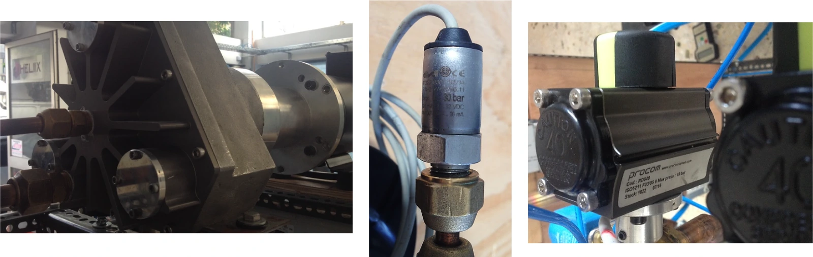
The PRC architecture brings together high- and low-pressure buffer vessels, heat exchangers, an expander and a coordinated valve network. During the steady phase, vapor is guided through the expander to produce shaft work while the buffer vessels manage liquid supply and return. During the switching phase, valve states change in sequence so the hot and cold buffer roles are exchanged while limiting disruption to power production.
This design approach improves the practicality of low-grade heat recovery by reducing system complexity and avoiding a dedicated pump. It is especially relevant for distributed waste-heat recovery, renewable thermal sources and low-power installations where robust hardware, modest maintenance and cost-effective control are more important than high power density.
System Modelling and Experimental Validation
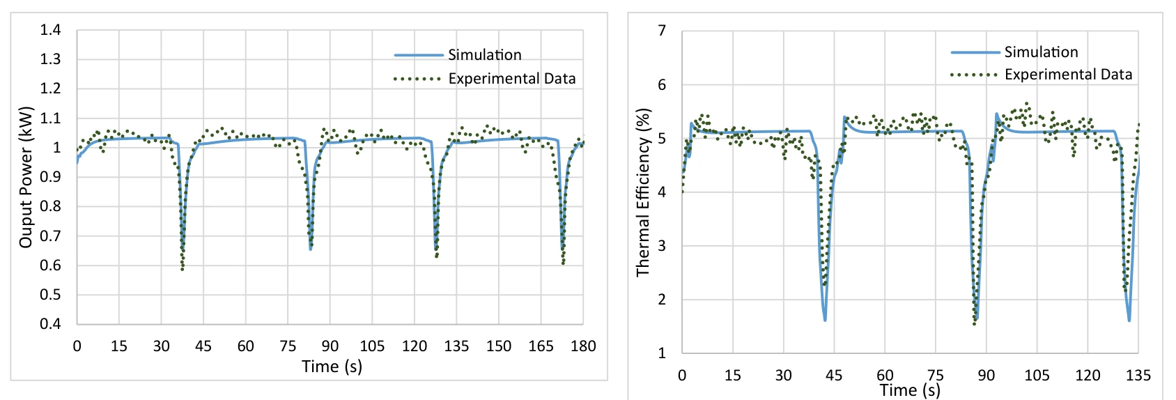
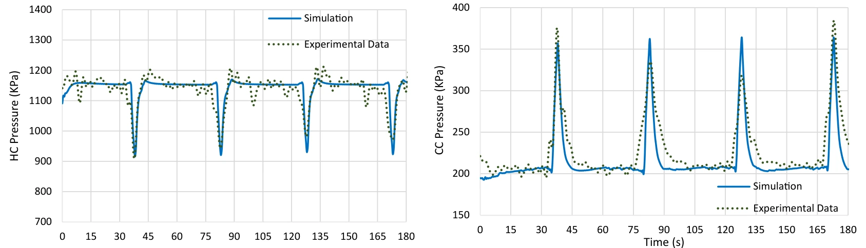
The project model links the thermodynamic, fluidic and mechanical subsystems through algebraic and ordinary differential equations. The system was solved numerically using parameters from the experimental R245fa setup, allowing pressure evolution, expander speed, output power and thermal efficiency to be compared directly with measured data.
The results show that the model captures the main dynamic behavior of the cycle, including the pressure drops and spikes associated with repeated switching. Experimental operation demonstrated stable output with time-averaged efficiency near 4.8% and a maximum experimental efficiency of 5.1%. The validated workflow also supports future improvements in buffer sizing, heat-exchanger placement, valve timing and automatic control.