Electromechanical APPLICATIONS
Mavrakeios School
Electromechanical application-stage design for adaptive reuse into a research, innovation and learning center
MD-Lab contributed the electromechanical design package for the adaptive reuse of the Mavrakeios School in Elliniko, Gortynia, supporting its transformation into a mixed research, learning and public-activity hub. The work coordinated electrical infrastructure, HVAC, water supply, drainage, active and passive fire protection, lightning protection, grounding and lift design across one integrated application-stage building-services package.
Scope
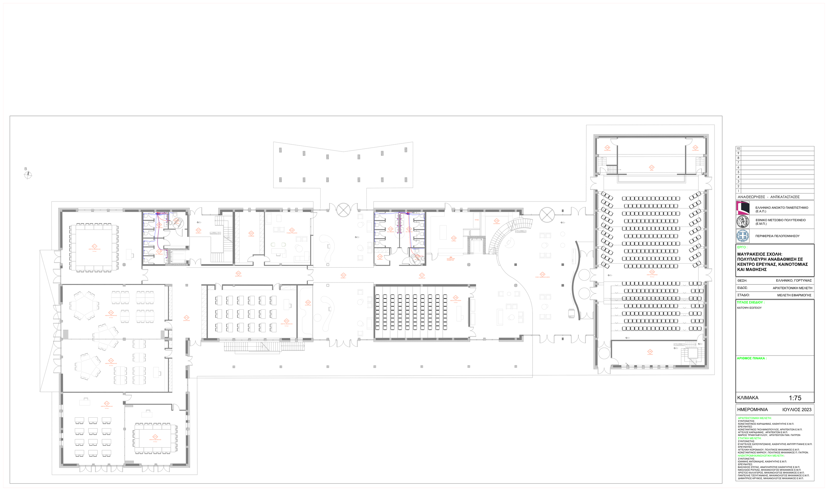
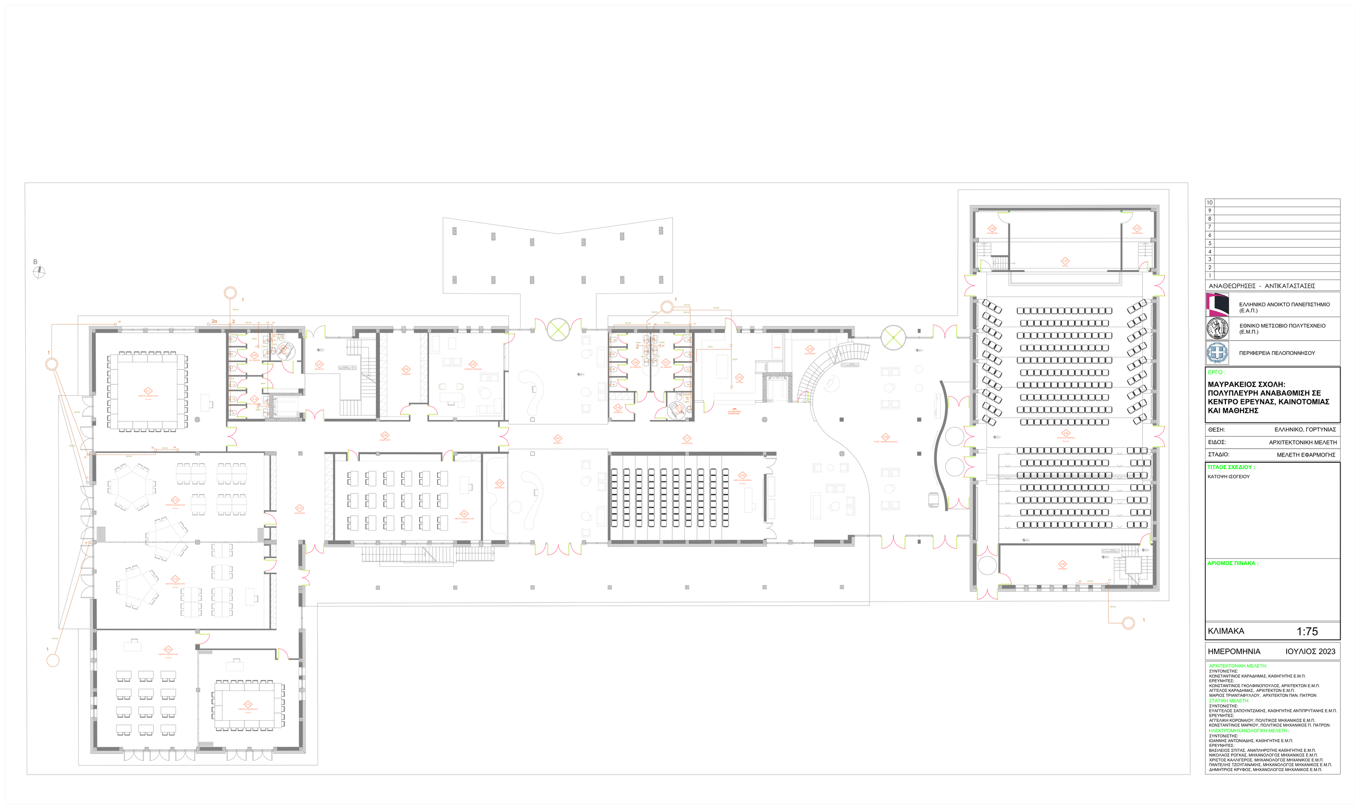
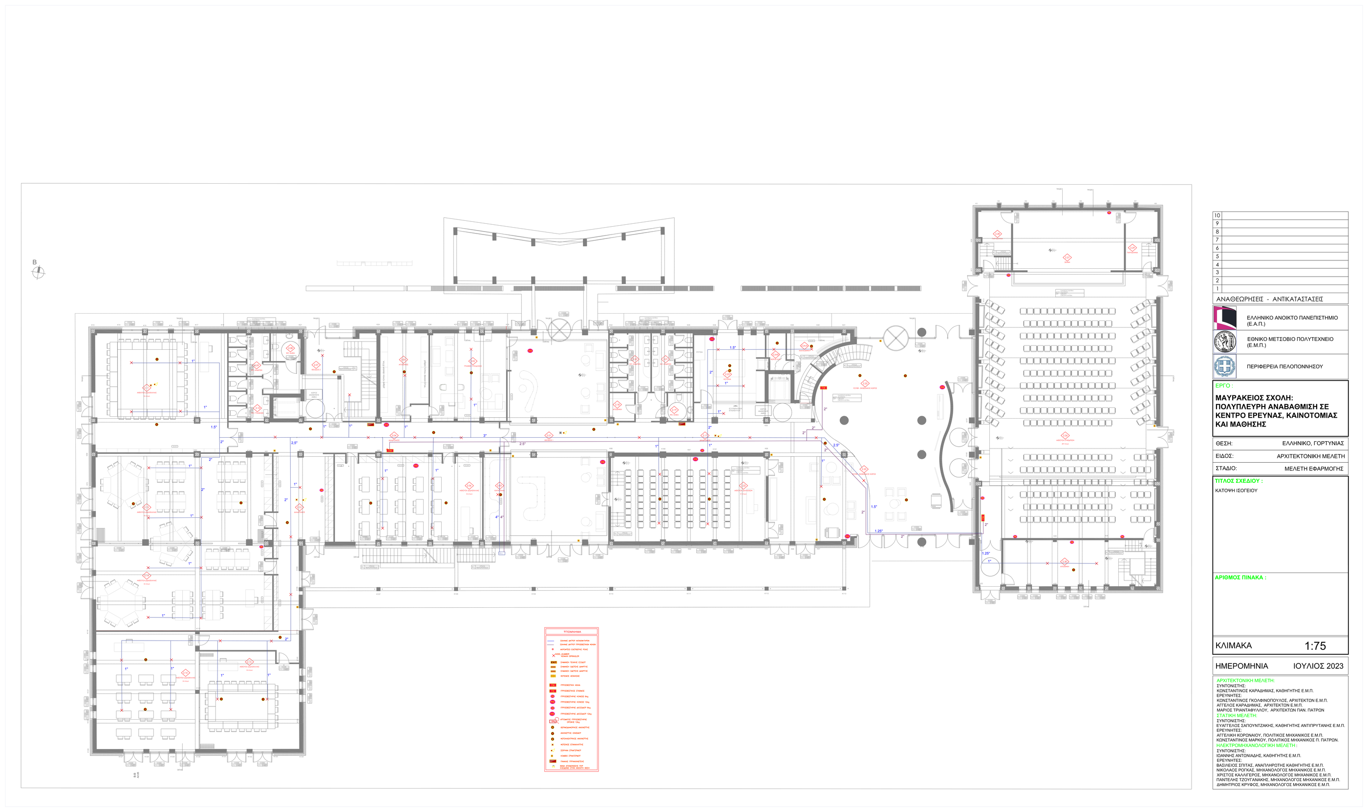
The electromechanical package forms part of a broader redevelopment strategy for the Mavrakeios School. Rather than treating the services as isolated discipline drawings, the design ties them to a mixed-use program that combines education, assembly, dining, office and learning-support spaces inside one adaptive-reuse building.
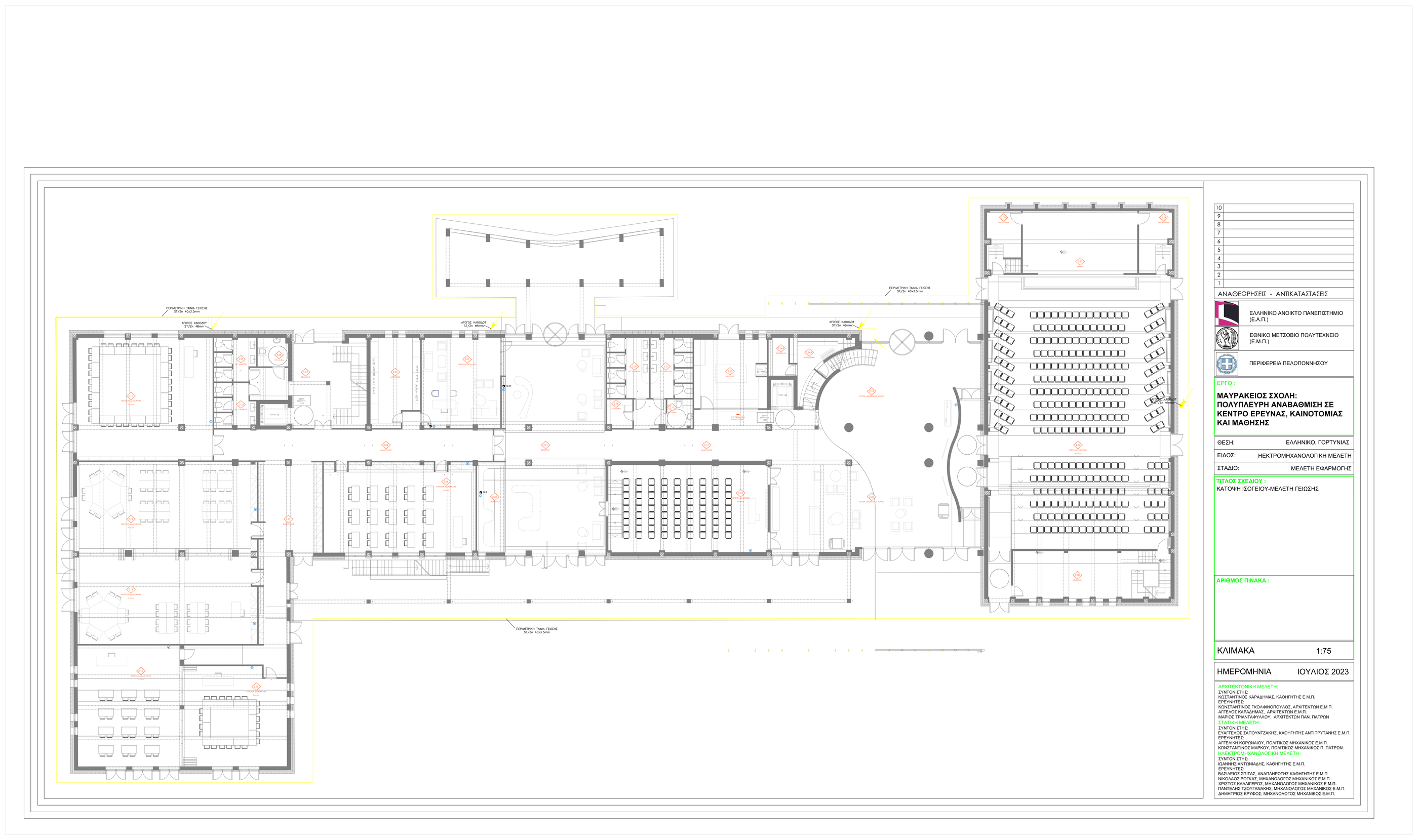
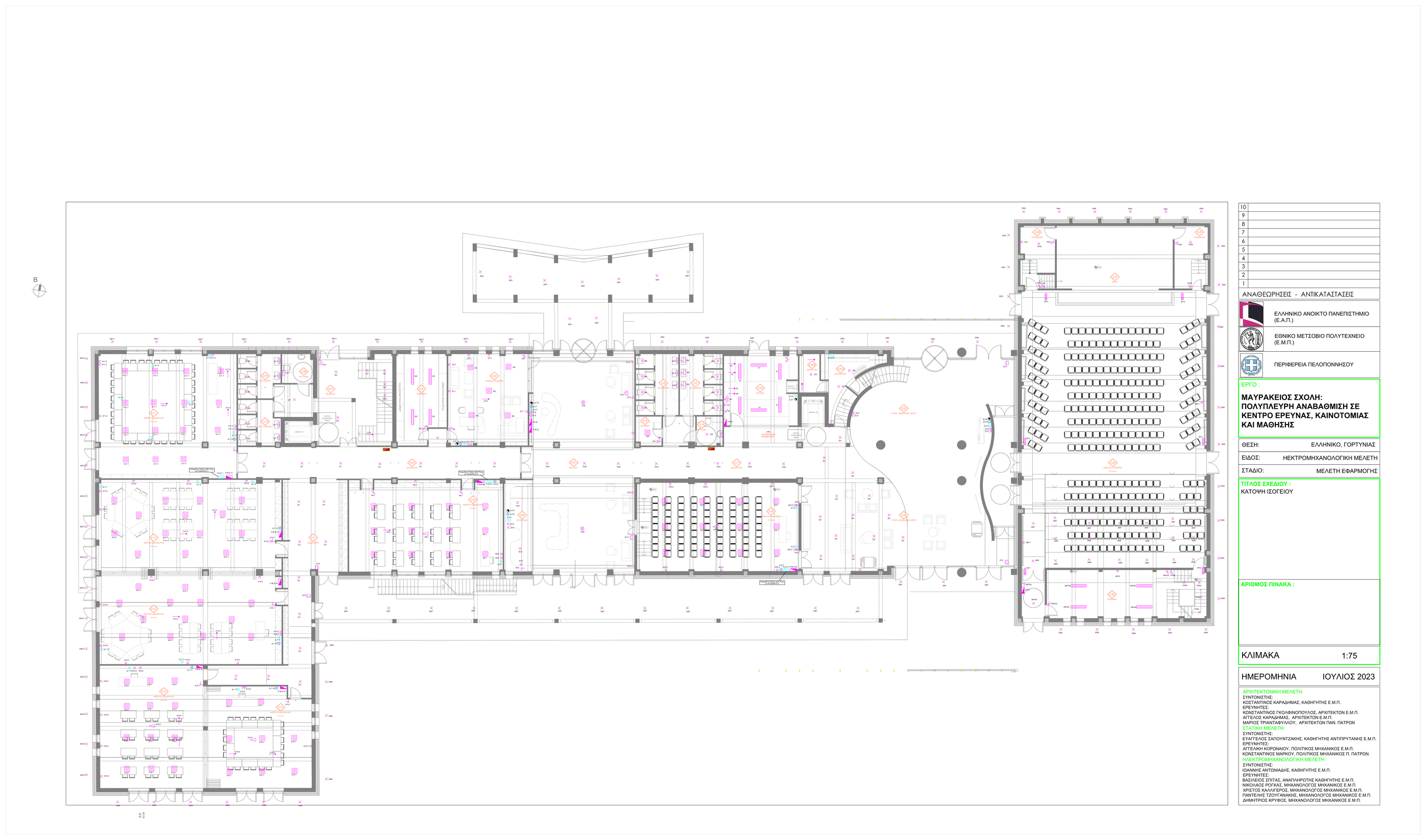
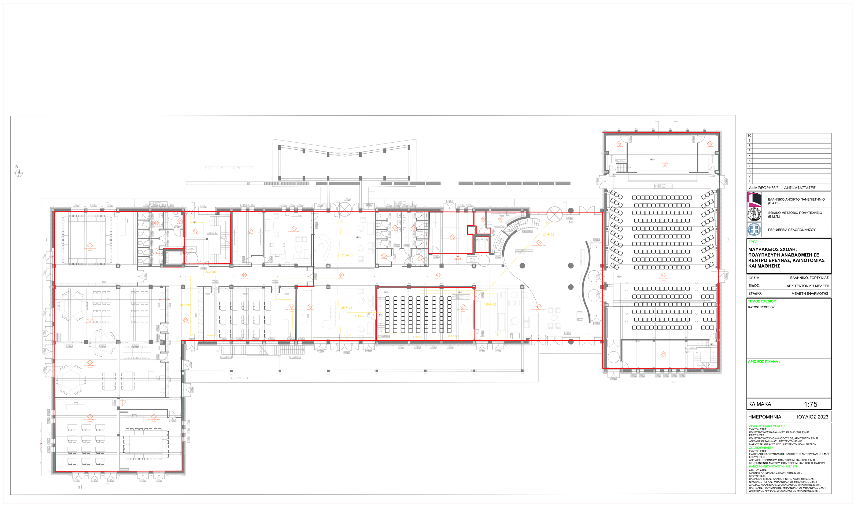
That demanded coordination across several technical layers at once: power and lighting, heating and ventilation, potable water, sanitary discharge, firefighting, egress logic, grounding and vertical transport. The drawing package covers basement, ground-floor, first-floor and roof conditions so that the service routes could be checked against the actual architectural geometry rather than only against abstract load tables.
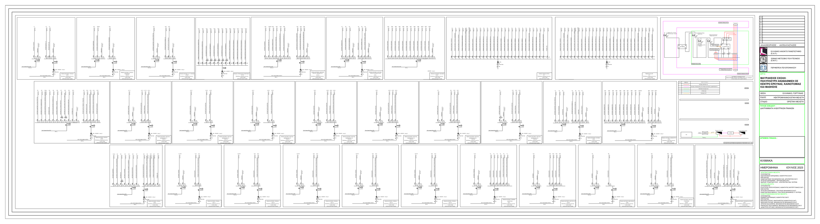
- Application-stage electrical design based on ELOT 60364:2020 and coordinated panel schedules.
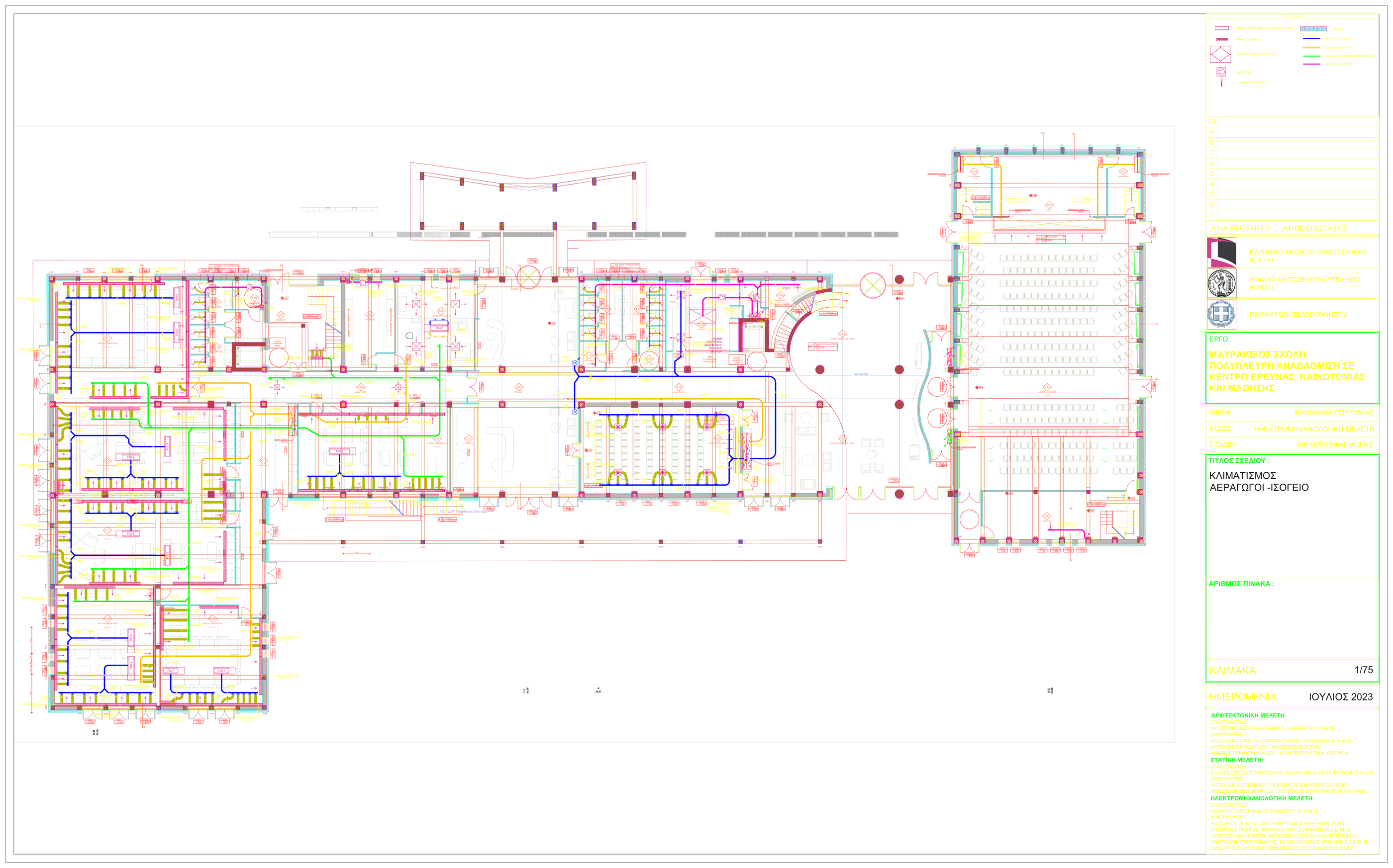
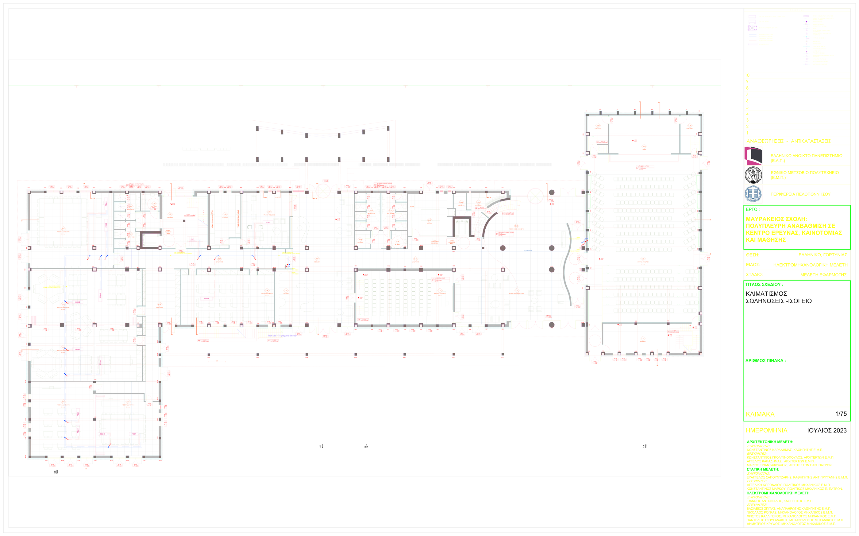
- HVAC layouts for ducts and pipes alongside calculation notes for design conditions, air requirements and thermal loads.
- Water-supply and drainage networks developed through hydraulic sizing logic tied to the building-use profile.
- Active and passive fire-protection design integrated with circulation, exits and service infrastructure.
Coordinated Service Strategy
The most useful quality of the electromechanical package is how it turns the reuse brief into a set of mutually aware building systems. The electrical and mechanical layers do not sit beside the architectural work as afterthoughts; they define how the future learning, conference and support spaces can actually operate day to day.
Electrical Infrastructure
Lighting, power distribution and panel logic were organized into a coordinated internal-installation package.
Climate Control
Duct and pipe networks were sized against internal conditions, ventilation demand and thermal-load assumptions.
Hydraulic Networks
Water-supply and drainage routes were laid out as full building networks rather than isolated room-by-room fixes.
Fire and Resilience
Sprinkler and hose-reel logic, compartmentation, exits, grounding and lightning protection were treated as one safety layer.
Electrical and Mechanical Design
The electrical design follows a conventional but carefully structured internal-installation workflow grounded in ELOT 60364:2020, supporting circuit organization, equipment loads and panel distribution for the reused building. In parallel, the HVAC package develops the heating, cooling, ventilation and air-distribution strategy by linking internal and external design conditions, building-envelope assumptions and occupancy-related loads.
Together, those two layers establish the operational backbone of the project. The electrical sheets describe how the spaces are powered and controlled, while the HVAC package shows how air and thermal services move through the same plan geometry without losing coordination with circulation zones, room subdivisions or major public-use areas.
- Ground-floor electrical layouts organize fixtures, outlets and branch circuits against the reuse plan.
- Panel-diagram sheets consolidate the switching and protection logic behind the internal electrical network.
- HVAC drawings separate duct and pipe layers so coordination can be checked clearly at sheet level.
Water, Drainage and Fire-Protection Networks
The hydraulic systems treat the building as a full service ecosystem rather than a sequence of local plumbing decisions. The water-supply network uses standard demand and peak-flow logic to size cold- and hot-water branches, while the drainage network organizes horizontal runs, stacks and ventilation logic across the occupied levels.
Fire protection extends that logic into safety systems. The active-fire network is organized around a permanent water firefighting system, using sprinkler and hose-reel assumptions tied to NFPA13-style sizing logic, while the passive-fire layer checks compartmentation, escape routes, exits and signage against the building’s mixed-use occupancy model.
- Water and drainage drawings keep the wet-network geometry aligned with the architectural room structure.
- Active-fire layouts distribute firefighting coverage within the same coordinated plan framework.
- Passive-fire analysis addresses compartmentation, exit widths and user evacuation paths.
Safety Logic, Grounding and Delivery Context
The fire-safety layer adds particularly useful building-level constraints to the package. It works with a mixed-use occupancy model spanning education, assembly, dining and office-type functions, and uses a total theoretical population of 870 people. From that basis, the design defines egress-width requirements, confirms dual stair logic at upper level, and identifies a required total final-exit width of 6.6 m.
Alongside those fire and circulation checks, the drawing set also includes dedicated lightning-protection and grounding plans plus a separate lift package. That combination matters because it shows the package was delivered as a real application-stage services set: not only comfort and utilities, but also resilience, code alignment and vertical movement for the upgraded facility.
- The compartmentation strategy targets 90-minute resistance in the main enclosure logic, with localized stronger requirements handled through system coordination.
- The active-fire calculations assume permanent water-based firefighting infrastructure with sprinklers and hose reels.
- The lift package extends the electromechanical scope into vertical transport, complementing the horizontal service-network package.