Gearless Differential
Rolling-Contact Gearless Automotive Differential
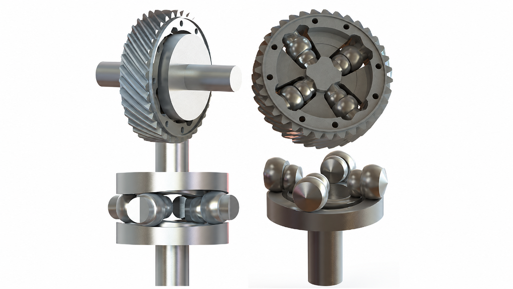
The Gearless Differential project investigates a cam-track differential architecture that replaces conventional side and spider gears with identical wavy cam-track disks, guided rolling members and a geared retainer. The work formalizes the geometry required for rolling contact, verifies the kinematics through simulation, and evaluates a representative passenger-car configuration using contact stress and fatigue-life assessment.
Project Scope and Engineering Problem
The project revisits a gearless differential concept introduced by Theodore Tsiriggakis and places it within a rigorous machine-elements framework. An earlier prototype was road-tested in a PYRCAL vehicle under PYRCAL SA supervision in Greece; the testing was certified on 1 November 1983 after at least 15,000 km in all road conditions. The later research asks what geometry and loading conditions would be needed for such a mechanism to work as a rolling-contact drivetrain component.
Conventional automotive differentials rely on meshing gears to transmit torque while allowing the two driven wheels to rotate at different speeds. Gear contacts introduce sliding, backlash and dynamic excitation, while the mechanism itself remains mechanically complex. The gearless concept is technically significant because it explores whether the bearing principle can be generalized from circular raceways to wavy cam tracks that transmit torque through rolling members.
MD-Lab’s Contribution
The work was carried out by researchers of the Machine Design Laboratory led by Prof. Christopher G. Provatidis. MD-Lab contributed the analytical framing of the cam-track geometry, the kinematic interpretation of the rolling elements, the simulation studies and the finite element assessment of a representative automotive design.
The contribution is deliberately engineering-focused: it does not rely on broad claims about self-regulation, but evaluates the mechanism through track geometry, contact conditions, load sharing, local stresses and fatigue-life assumptions that can be checked and refined by future design work.
Mechanism Architecture
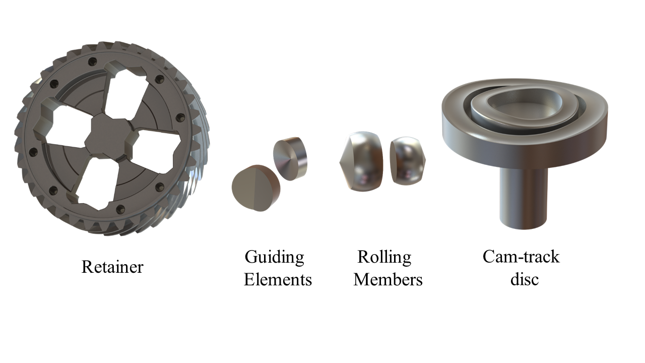
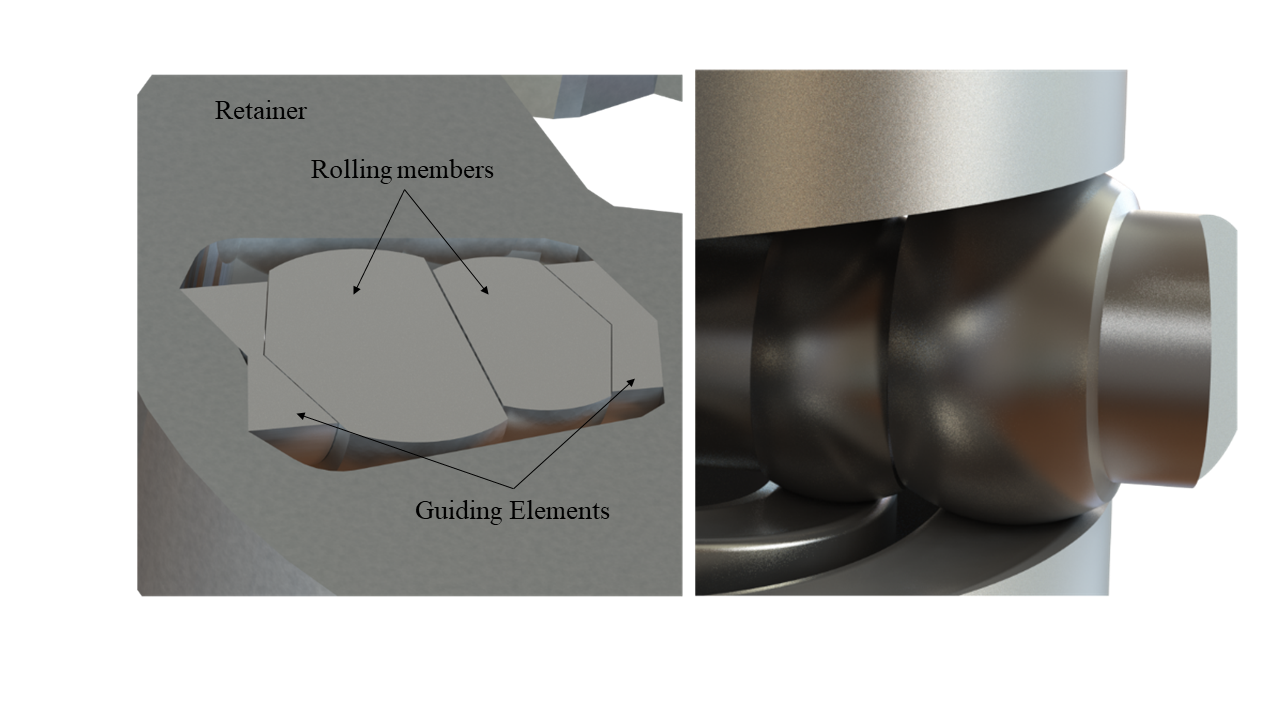
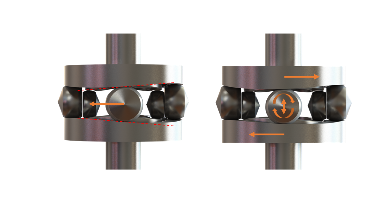
The proposed mechanism replaces the side gears of a conventional open differential with two identical cam-track disks. The spider gears are replaced by axisymmetric rolling members, while a geared retainer and V-shaped guiding features organize the motion of the rolling members around the mechanism axis.
In straight-ahead operation, the assembly behaves like a locked drivetrain component: the retainer, rolling members and cam-track disks rotate together. During differential action, the cam-track disks can rotate relative to one another while the rolling members spin and shift along the guide direction, maintaining contact with the opposed wavy tracks.
Rolling-Contact Kinematic Procedure
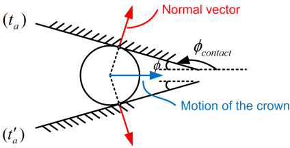
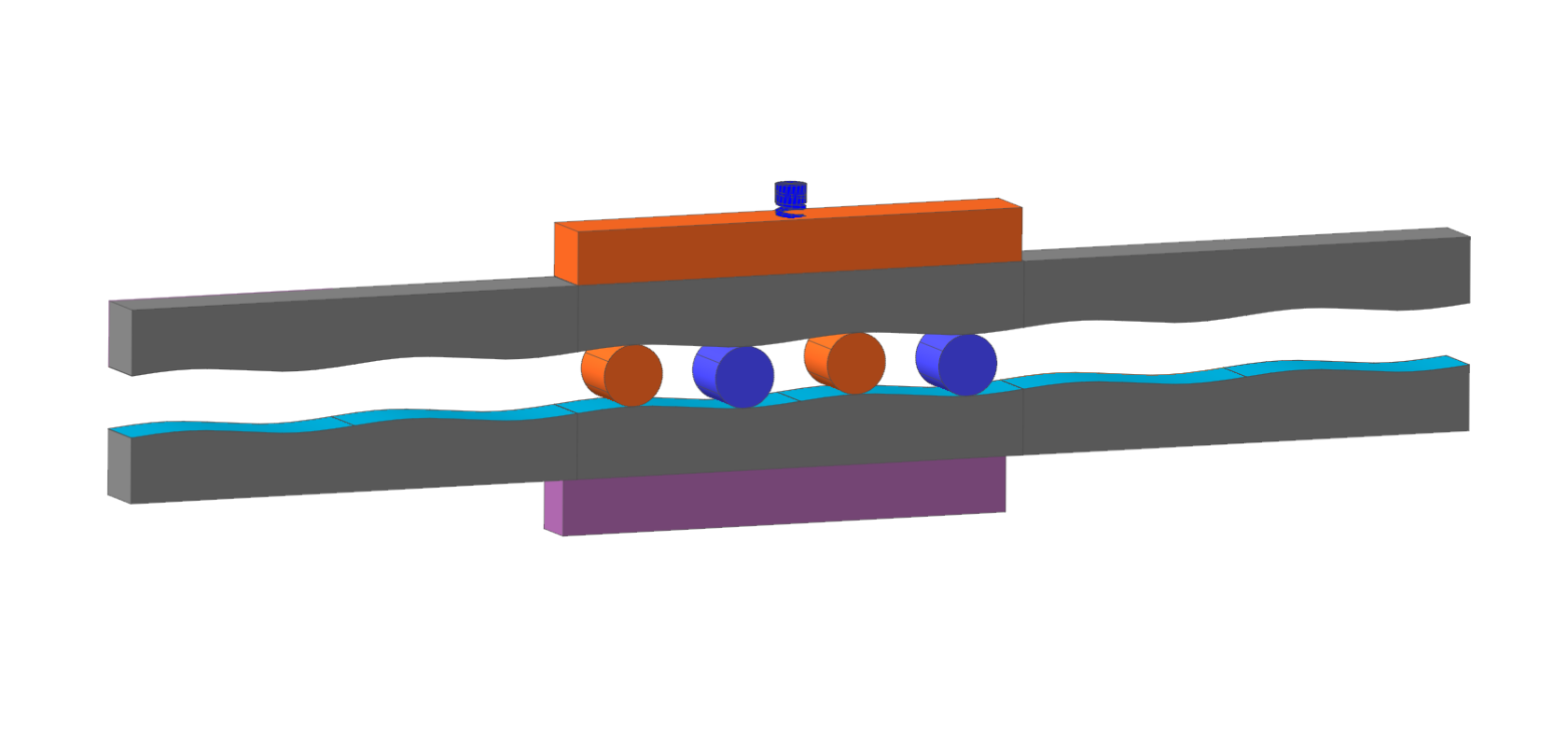
The procedure defines the cam tracks from periodic wavy midlines and their offset curves, including circular-arc and sinusoidal definitions, so that a circular cutter or follower can generate conjugate track surfaces.
The key engineering result is that rolling contact is not automatic; it depends on symmetry and phasing of the cam-track midlines. Under the studied conditions, the rolling members can rotate while oscillating in the guide direction, creating differential motion without requiring the conventional side-gear and spider-gear mesh.
Contact and Fatigue Evaluation
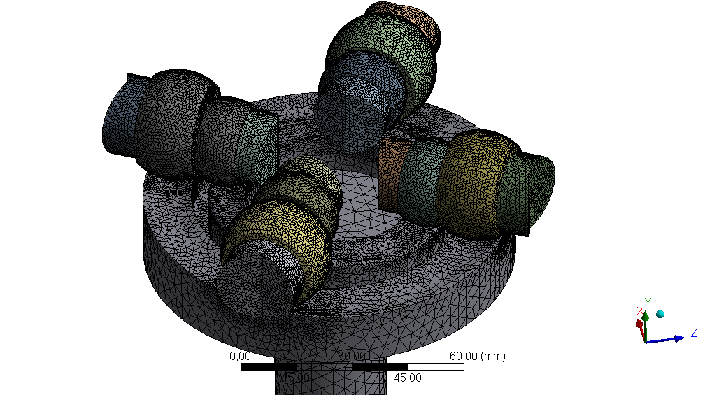
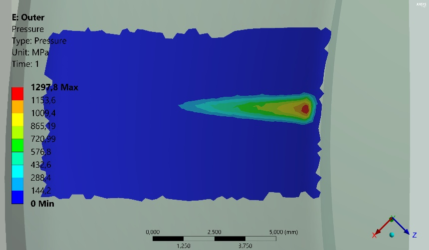
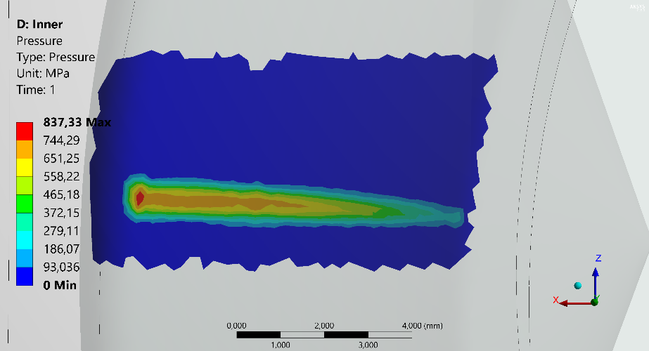
The procedure then evaluates a passenger-car-scale mechanism using finite element contact analysis. A representative torque load of 260 Nm was used to identify the highly loaded contact zones between the rolling members and the inner and outer cam tracks.
The analysis indicates that the most severe contact stresses occur when only two rolling members contribute to torque transmission. In that phase, the outer cam-track contact region reaches the highest pressure level, while the inner track is less severe. A Miner-type fatigue interpretation, using bearing-steel pressure limits and a simplified vehicle-use assumption, gives a service-life estimate on the order of 200,000 km for the examined configuration.
Engineering Significance
The study matters for drivetrain and machine-element design because it converts a historically tested gearless concept into a geometry-driven and simulation-supported engineering problem. It clarifies what must be true for rolling contact to be plausible, how the rolling members participate in torque transfer, and where the critical contact stresses appear.
Beyond the automotive differential, the same design logic points toward broader cam-based power-transmission mechanisms, reducers and compact drives where backlash, gear-mesh sliding or conventional planetary layouts are limiting factors. The immediate value is not a finished production differential, but a validated design framework that connects kinematics, contact mechanics and fatigue assessment.