External Heat Engines Modelling
External Heat Engines: Stirling and Ericsson Engine Modelling
MD-Lab research on external heat engines develops design-oriented thermodynamic models for Stirling and Ericsson machines. The work focuses on transient heat transfer, real-cycle losses, valve timing and experimentally grounded performance prediction for engines that can use external heat sources such as waste heat, solar thermal energy, biomass and combustion outside the working volume.
Research Scope
Stirling and Ericsson engines separate heat addition from the working-fluid expansion process. This gives them unusual fuel and heat-source flexibility, but also makes their performance highly dependent on finite-rate heat transfer, thermal inertia, pressure losses, regenerator behavior and transient operation. Ideal cycles are useful for interpretation, yet they are not sufficient for sizing real machines.
MD-Lab addresses this design gap with analytical and numerical models that resolve the dominant real-cycle mechanisms while remaining fast enough for parameter studies. The objective is to support early-stage decisions on geometry, speed, pressure level, heat-exchanger temperature, loss mechanisms and timing before moving to more expensive numerical simulations or experimental prototypes.
MD-Lab’s Contribution
The research program connects thermodynamic cycle analysis with machine-design modelling:
- Second-order transient thermal modelling of beta-type Stirling engines, including time-varying losses and solid-wall thermal response.
- Prediction of Stirling engine start-up, steady-state power and thermal efficiency through coupled mass and energy balances.
- Time-dependent Ericsson-engine modelling with valve-flow calculation, cylinder-wall heat transfer and piston kinematics.
- Valve-timing optimization and backflow diagnosis for Ericsson-engine efficiency improvement.
Stirling Engine
Transient Thermal Modelling
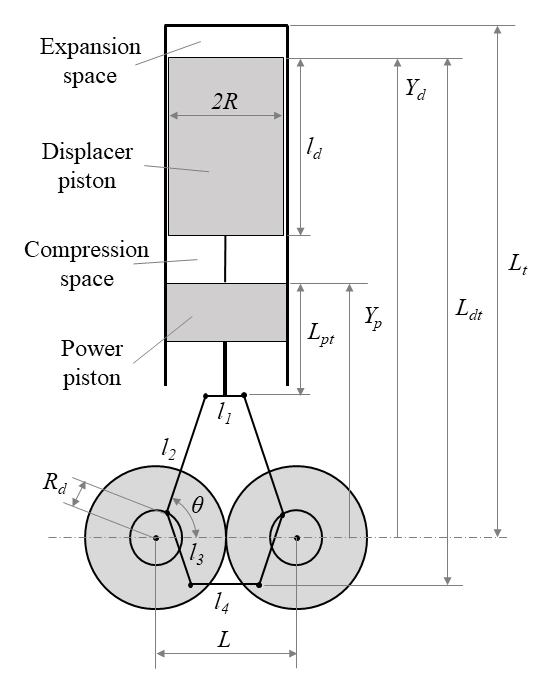
The Stirling engine operates by cyclically compressing and expanding a sealed working gas while heat is supplied externally through a heater and rejected through a cooler. In beta-type engines, a displacer transfers the gas between hot and cold regions while a power piston extracts mechanical work. A regenerator stores and returns heat between strokes, making the Stirling cycle attractive for high theoretical efficiency and multi-source heat utilization.
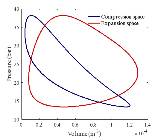
MD-Lab’s Stirling-engine work focuses on a second-order transient thermal model for beta-type machines. The model divides the engine into compression space, cooler, regenerator, heater and expansion space, then solves the coupled mass and energy balances through time. Unlike ideal-cycle models, it tracks the thermal response of cylinder walls, pistons and heat exchangers, which is essential for predicting start-up behavior and the eventual steady-state operating point.
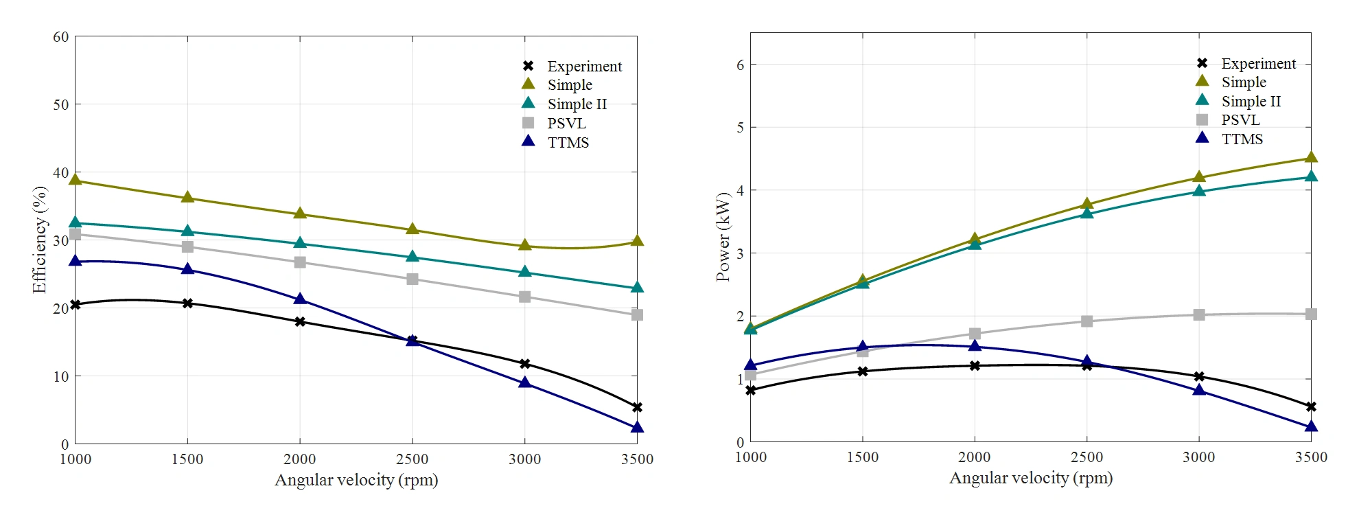
The model incorporates relevant loss mechanisms, including shuttle heat transfer, leakage, regenerator losses and pressure-drop effects. Applied to the GPU-3 benchmark engine, the approach improves agreement with experimental power and efficiency data compared with simpler second-order formulations.
Ericsson Engine
Valve Timing and Time-Dependent Heat Transfer
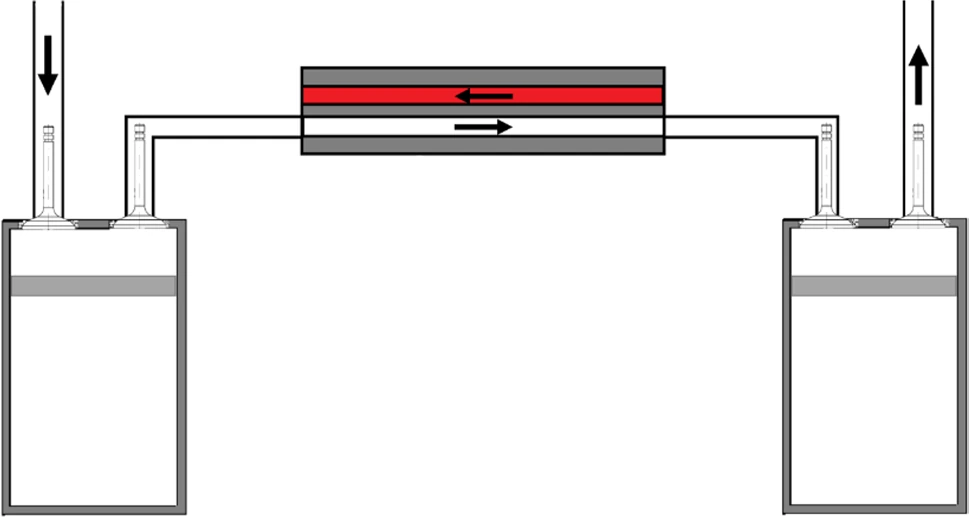
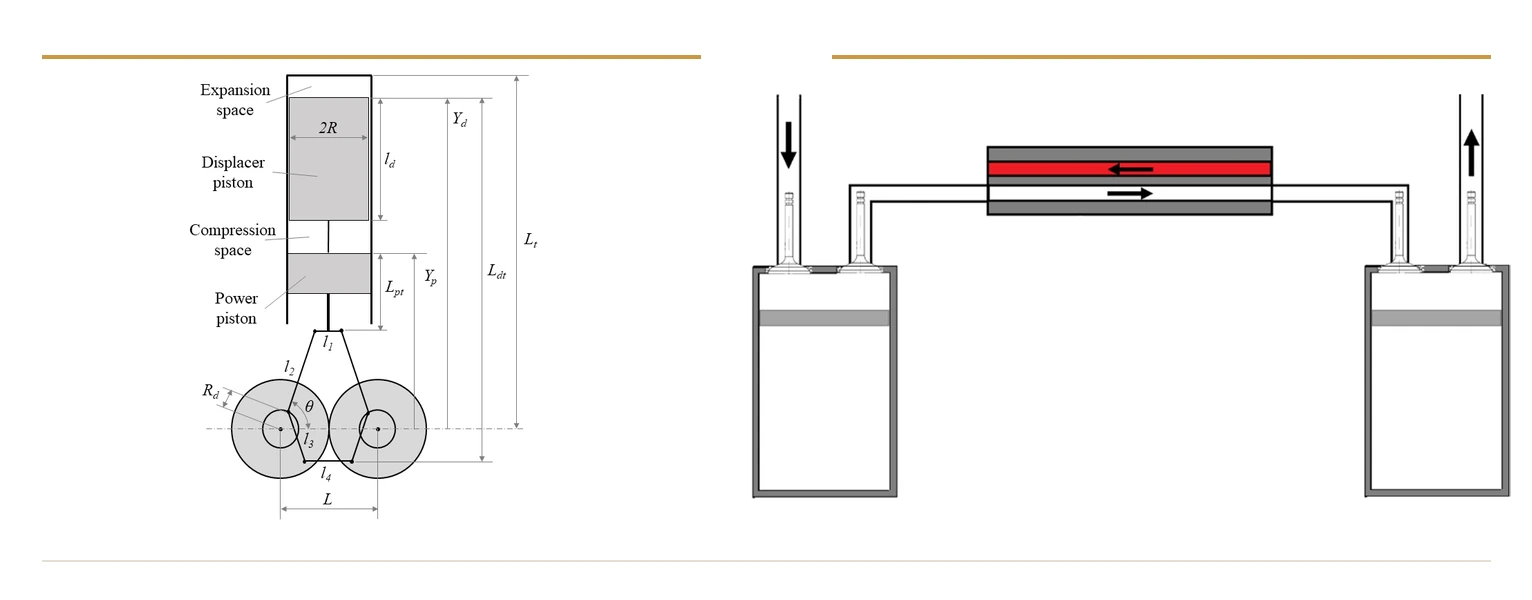
The Ericsson engine uses separate compression and expansion cylinders connected through external heat exchange. The working gas is compressed, heated in a heat exchanger, expanded to produce work and often routed through a regenerator to recover exhaust heat. Its practical performance depends strongly on cylinder geometry, crank-slider kinematics, heat-exchanger temperature, rotational speed and valve timing.
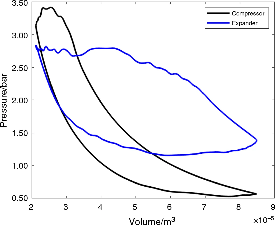
MD-Lab developed a time-dependent analytical model that calculates gas pressure and temperature in each cylinder at every time step. The formulation couples open-system energy balance, ideal-gas behavior, piston motion and a valve-flow model that accounts for pressure drop through the inlet and exhaust valves. This produces steady-state pressure-volume diagrams and thermal-efficiency estimates without the computational burden of fully resolved valve CFD.
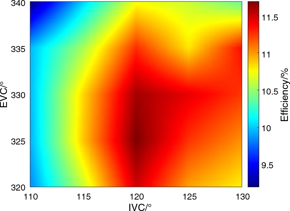
The research shows that valve timing is a first-order design variable. In the studied case, thermal efficiency reached the 10-14% range under high heat-exchanger temperatures and could be increased significantly through timing optimization. The model also identifies backflow events and pressure mismatches between cylinders and heat exchanger.