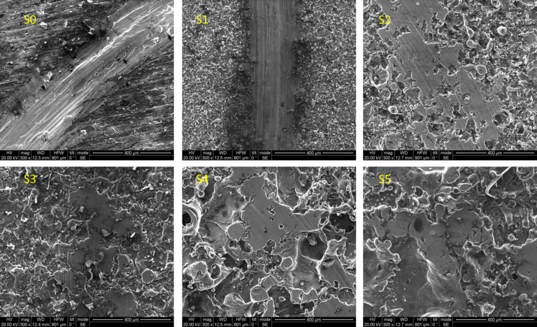
LESS Mechanism
Numerical Investigation of the LESS Mechanism

The LESS project examined a patented power-transmission mechanism proposed as an alternative to conventional crank-rod systems in reciprocating machines. The mechanism converts rotary to reciprocating motion and vice versa, with potential use in internal-combustion engines, pumps, compressors, and expanders. MD-Lab contributed by building the numerical modelling chain required to study contact, friction, and lubrication behavior.

Mechanism Scope
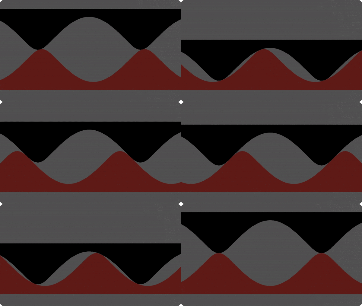
The LESS mechanism was studied as a power-transmission architecture that could replace a conventional crank-rod mechanism in engines or similar reciprocating machines. The concept is based on ring-like components with undulated meshing surfaces that slide relative to each other, allowing rotary and reciprocating motion to be coupled through the selected surface topology.
The mechanism targets applications such as internal-combustion engines, pumps, compressors, and expanders. Its potential depends not only on the intended kinematic and thermodynamic advantages, but also on whether the profiled contact surfaces can operate with acceptable internal losses.
MD-Lab investigated how the meshing surfaces interact during an operating cycle, how loads are shared between contact points, how contact pressures and sliding velocities can be estimated, and how lubrication models can be used to assess friction-related design questions.
Numerical Modelling Workflow
MD-Lab developed the numerical workflow needed to connect the geometry of the LESS profiles with mechanical and tribological quantities. The first model calculated the relative position of the moving and stationary profiles and identified the active contact points for each stage of operation. The contact-search process was implemented numerically and optimized so that large parametric studies could be performed with reasonable computational cost.
A second modelling layer distributed the applied load between the active contact points and estimated local contact conditions. The analysis combined profile curvature, material assumptions, component width, contact forces, Hertzian contact pressure calculations, and sliding velocities. These outputs provided the inputs for friction and lubrication assessment.
Lubrication Model Framework
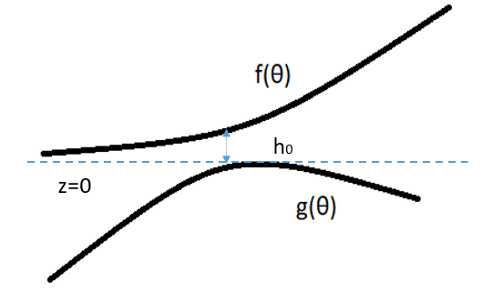
The lubrication work moved from a qualitative friction screening to a dedicated 2-D lubrication model. Early friction estimates used Stribeck-curve concepts to classify operating regimes and to support model development. The more detailed lubrication model started from simplified Navier-Stokes assumptions and derived a Reynolds-type formulation in polar coordinates for the local film between the moving and fixed surfaces.
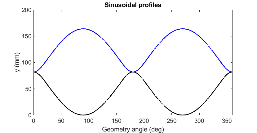
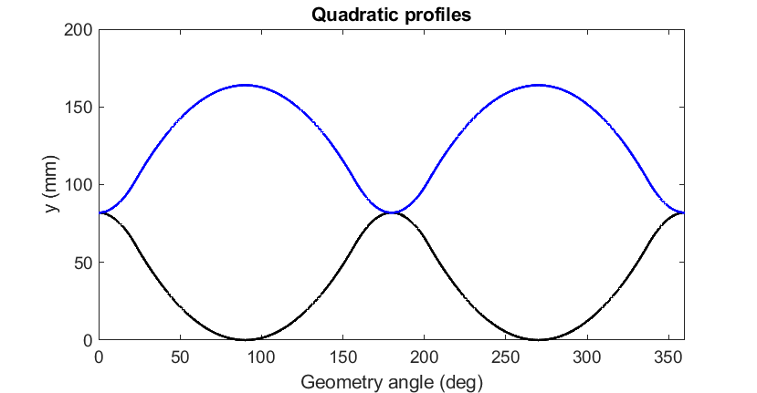
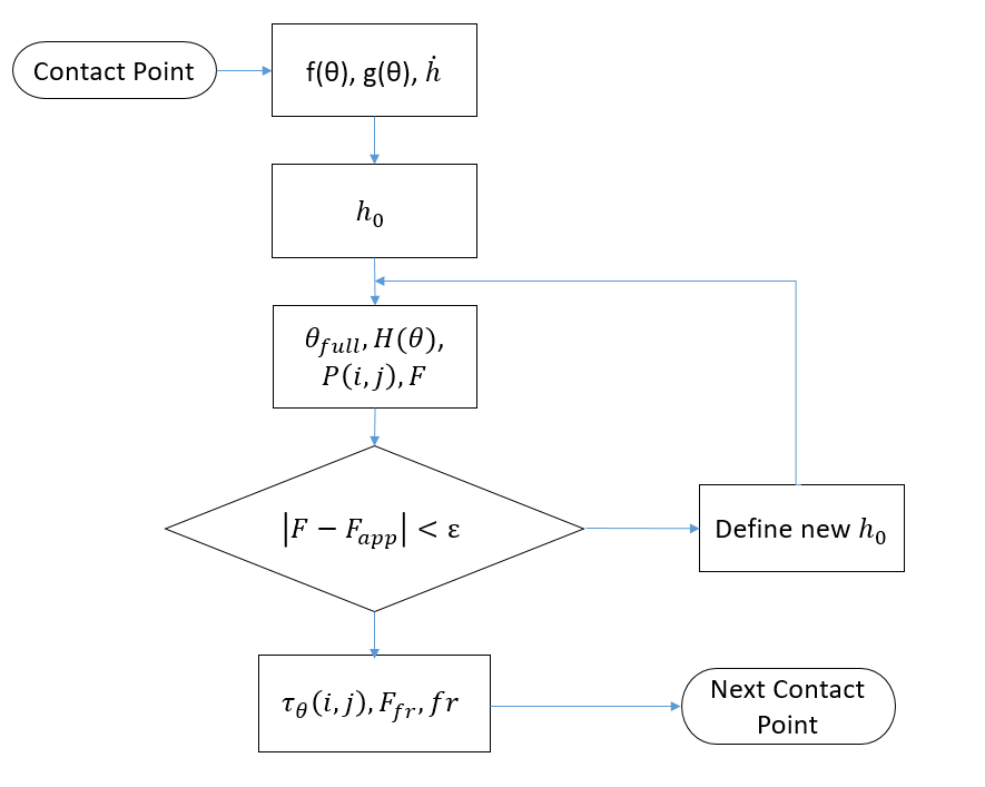
The model was generalized so that the surface topology could be supplied either as analytical functions or as point data. For each contact point, the solver estimated the flooded angular region, film thickness, pressure field, shear stress field, friction force, and equivalent friction coefficient through a finite-element discretization and convergence loop.
CFD Lubricant-Domain Simulation
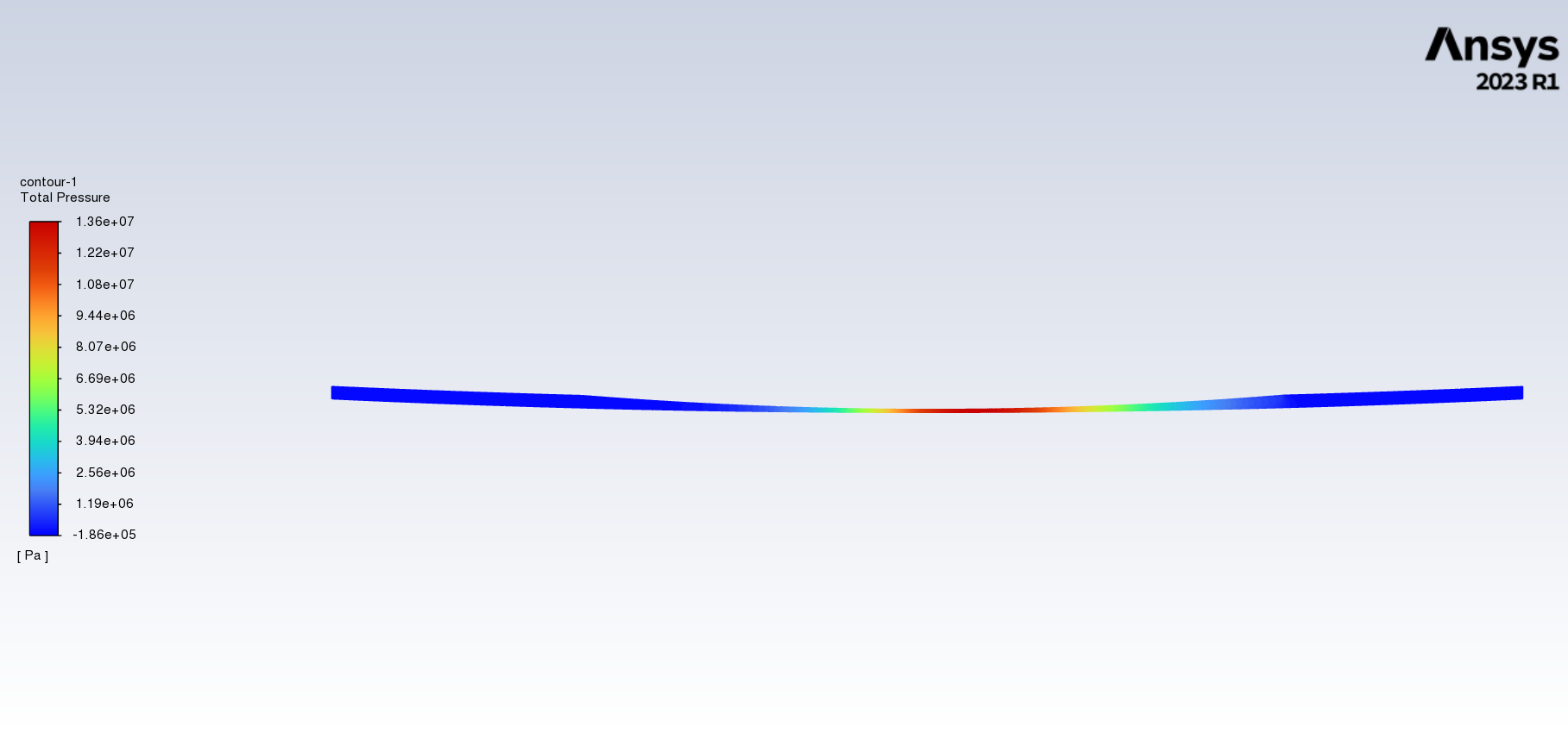
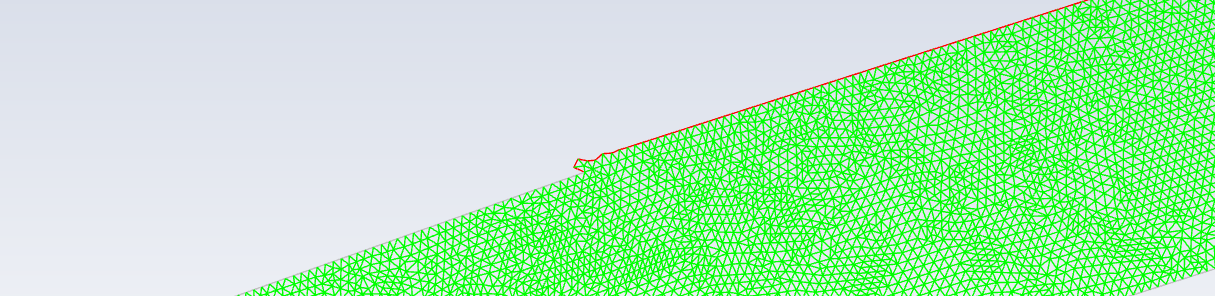
MD-Lab also investigated the lubricant domain using transient CFD simulation. Because the real mechanism involves non-conformal surfaces, very thin oil-film regions, and moving boundaries, the modelling strategy used a 2-D linear analogue with a dynamic mesh. This made it possible to study the local fluid domain with a manageable computational model while preserving the essential profile interaction.
The CFD work was carried out in ANSYS Fluent. The simulated domain included stationary and moving walls, pressure boundaries, prescribed wall velocities, and a transient remeshing strategy. The objective was to examine pressure, velocity, shear-stress, and mesh-deformation behavior inside the lubricant film as part of the internal design study.
Specific numerical results, parameter rankings, friction-loss values, operating-regime maps, and conclusions about the LESS mechanism are intentionally omitted due to confidentiality.